
Table 7-5
Power Supply Cable Connectors
Power Supply Connector
Power Cable Connector
Label
System Board
Connector
Label
6-pin, white
P1
PWR
6-pin, white
P2
PWRCMD
4-pin, white
P3
PWRCPU
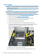
CAUTION:
When installing the power supply cables, make sure they are properly positioned so
they are not cut by the drive cage and are not pinched by the rotating power supply.
System Board
1.
Prepare the computer for disassembly (
Preparation for Disassembly on page 90
).
2.
Remove the access panel (
Computer Access Panel on page 99
).
3.
When replacing the system board, make sure the following components are removed from the
defective system board and installed on the replacement system board:
●
Memory modules (see
Installing Additional Memory on page 102
)
●
Expansion cards (
Expansion Cards on page 106
)
●
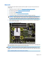
Heat sink (
Heat sink on page 137
)
●
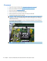
Processor (
Processor on page 138
)
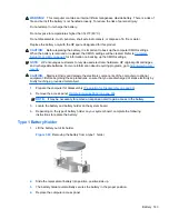
4.
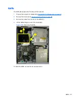
Remove the baffle from the chassis (
Baffle on page 131
).
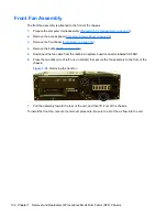
5.
Remove the fan from the chassis (
Front Fan Assembly on page 132
).
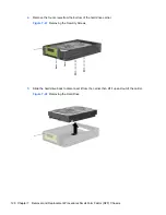
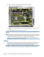
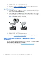
6.
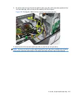
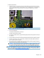
Rotate the drive cage to its upright position.
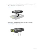
7.
Rotate the power supply to its full upright position.
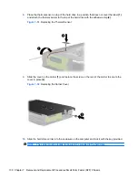
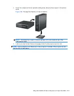
8.
Disconnect all data and power cables from the system board.
9.
Disconnect the balance of the cables from the system board.
System Board 141


