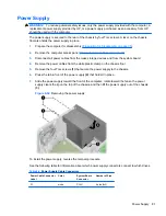
Power Cable Connector
Label
Color
System Board
Connector
Number of Pins
P2
white
PWRCMD
6 pins (1x6)
P3
white
PWRCPU
4 pins (2x2)
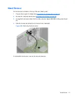
System Board
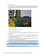
1.
Prepare the computer for disassembly (
Preparation for Disassembly on page 35
).
2.
When replacing the system board, make sure the following components are removed from the
defective system board and installed on the replacement system board:
●
Memory modules (
Installing Additional Memory on page 48
)
●
Expansion cards (
Expansion Cards on page 52
)
●
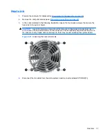
Heat sink (
Heat sink on page 77
).
●
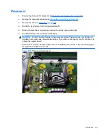
Processor (
Processor on page 79
)
3.
Remove the computer access panel (
Computer Access Panel on page 43
).
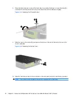
4.
Disconnect all cables connected to the system board, noting their location for reinstallation.
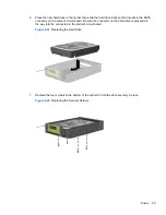
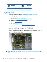
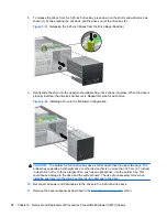
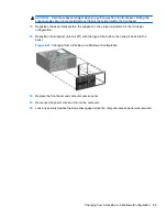
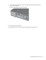
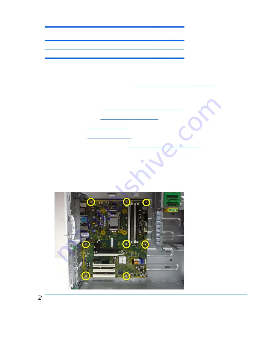
5.
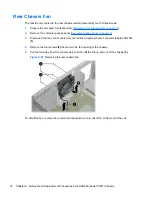
Remove the eight screws that secure the system board to the chassis.
6.
Slide the system board toward the front of the computer so that the connectors loosen from the
rear of the chassis, and then lift the system board out of the computer.
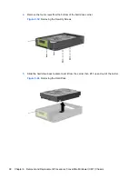
Figure 6-55
Removing the system board
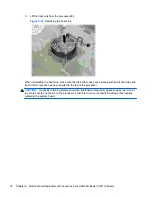
NOTE:
When replacing the system board, you must also change the chassis serial number in the
BIOS.
Table 6-5
Power Supply Cable Connectors (continued)
82
Chapter 6 Removal and Replacement Procedures Convertible Minitower (CMT) Chassis


