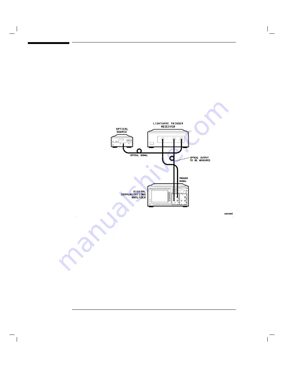
Connecting
the
HP
83447A
to
a
Digital
Communications
Analyzer
The
following
procedure
describes
how
to
connect
the
lightwave
trigger
receiver
to
a
digital
communications
analyzer
,
such
as
the
HP
83480A.
Refer
to
Figure
2-4
.
Figure
2-4.
Connecting
the
HP
83447A
to
a
digital
communications
analyzer
.
1.
Clean
all
connectors
before
connecting
them.
Refer
to
the
\Cleaning
Connections
for
A
ccurate
Measurements"
section,
later
in
this
chapter
for
instructions
.
Notice
that
the
connector
interface
has
a
small
protrusion.
This
protrusion
ts
in
the
slot
of
the
optical
connector
of
the
front
panel.
2.
Connect
an
optical
cable
from
the
OPTICAL
OUT
connector
on
the
lightwave
trigger
receiver
to
the
optical
data
input
connector
on
the
digital
communications
analyzer
.
An
adapter
may
be
necessary
.
3.
Connect
the
cable
from
the
laser
output
to
the
OPTICAL
IN
connector
interface
on
the
lightwave
trigger
receiver
.
2-10
Summary of Contents for 83447A
Page 1: ...User and Service Guide HP 83447A Lightwave Trigger Receiver ...
Page 3: ...Printing History HP Part Number Edition Date 83447 90002 Edition 1 April 1996 iii ...
Page 10: ......
Page 15: ...1 General Information ...
Page 25: ...Declaration of Conformity 1 11 ...
Page 29: ...2 Installation and Preparation for Use ...
Page 51: ...3 Using the HP 83447A ...
Page 55: ...4 Servicing the HP 83447A ...
Page 95: ...Servicing the HP 83447A Replaceable parts Figure 4 9 HP 83447A replaceable hardware 4 41 ...
Page 97: ...Index ...
Page 102: ...W warranty 2 13 warranty information viii waveform test measuring eye diagram 3 3 Index 6 ...


