7.
T
o
make
a
transmission
measurement
accurately
,
the
frequency
response
of
the
test
system
must
be
known.
T
o
measure
the
frequency
response
of
the
test
system,
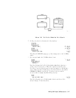
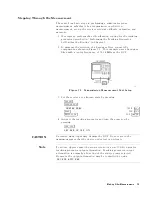
connect
the
cable
(but
not
the
DUT)
from
the
tracking
generator
output
to
the
receiver
input.
T
o
store
the
frequency
response
of
the
test
system
in
trace
B
,
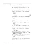
press:
4
TRACE
5
NNNNNNNNNNNNNNNNNNNNNNNNNNNNNNNNNNN
TRACE
A
B
C
B
NNNNNNNNNNNNNNNNNNNNNNNNNNNNNNNNNNNNNNNNN
CLEAR
WRITE
B
NNNNNNNNNNNNNNNNNNNNNNN
BLANK
B
8.
T
o
normalize
,
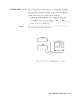
reconnect
the
DUT
to
the
receiver
and
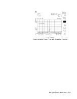
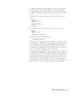
press:
4
TRACE
5
NNNNNNNNNNNNNNNNNNNNNNNNNNNNNNNNNNN
More
1
of
3
NNNNNNNNNNNNNNNNNNNNNNNNNNNNNNNNNNNNNNNNNNNNNNN
NORMLIZE
ON
OFF
ON
A
ctivate
the
display
line
by
pressing:
NNNNNNNNNNNNNNNNNNNNNNNNNNNNNNNNNNNNNNNNNNNNNNNNNNNNN
NORMLIZE
POSITION
The
display
line
marks
the
normalized
reference
position,
or
the
position
where
0
dB
insertion
loss
(transmission
measurements)
or
0
dB
return
loss
(reection
measurements)
will
normally
reside
.
Using
the
knob
results
in
a
change
in
the
position
of
the
normalized
trace
,
within
the
range
of
the
graticule
.
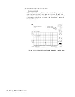
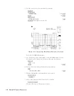
Set
the
level
so
it
is
one
graticule
below
the
top
of
the
display
.
Normalization
eliminates
the
frequency
response
error
of
the
test
system.
When
normalization
is
on,
trace
math
is
being
performed
on
the
active
trace
.
The
trace
math
performed
is
trace
A
minus
trace
B
plus
the
display
line
,
with
the
result
placed
into
trace
A.
Remember
that
trace
A
contained
the
measurement
trace
,
trace
B
contained
the
stored
calibration
trace
,
and
DL
(display
line)
represents
the
normalized
reference
position.
Note
that
the
units
of
the
reference
level,
dB
,
reect
this
relative
measurement.
Making
Other
Measurements
7-5


