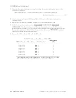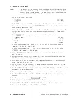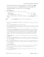
2.
600
MHz
Level
A
djustment
5.
Press
4
PRESET
5
on
the
host
spectrum
analyzer
and
set
the
controls
as
follows:
CENTER
FREQ
.
.
.
.
.
.
.
.
.
.
.
.
.
.
.
.
.
.
.
.
.
.
.
.
.
.
.
.
.
.
.
.
.
.
.
.
.
.
.
.
.
.
.
.
.
.
.
.
.
.
.
.
.
300
MHz
CF
STEP
.
.
.
.
.
.
.
.
.
.
.
.
.
.
.
.
.
.
.
.
.
.
.
.
.
.
.
.
.
.
.
.
.
.
.
.
.
.
.
.
.
.
.
.
.
.
.
.
.
.
.
.
.
.
.
.
.
.
.
300
MHz
SP
AN
.
.
.
.
.
.
.
.
.
.
.
.
.
.
.
.
.
.
.
.
.
.
.
.
.
.
.
.
.
.
.
.
.
.
.
.
.
.
.
.
.
.
.
.
.
.
.
.
.
.
.
.
.
.
.
.
.
.
.
.
.
.
.
.
20
MHz
6.
If
the
host
spectrum
analyzer
is
an
HP
8560A/E,
HP
8561B/E,
or
HP
8563A/E,
press
4
PEAK
SEARCH
5
4
CAL
5
NNNNNNNNNNNNNNNNNNNNNNNNNNNNNNNNNNN
REF
LVL
ADJ
.
If
the
host
spectrum
analyzer
is
an
HP
8561A,
HP
8562A,
or
HP
8562B
,
press
4
PEAK
SEARCH
5
4
AMPLITUDE
5
NNNNNNNNNNNNNN
MORE
NNNNNNNNNNNNNNNNNNNNNNNNNNNNNNNNNNN
REF
LVL
CAL
.
7.
Use
the
knob
or
step
keys
to
adjust
the
displayed
REF
LEVEL
ADJ
#
for
a
marker
amplitude
reading
of
010.00
dBm
60.17
dB
.
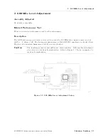
8.
Connect
the
62
cm
BNC
cable
between
the
host
spectrum
analyzer
CAL
OUTPUT
and
the
tracking
generator
300
MHz
INPUT
.
Connect
the
122
cm
BNC
cable
between
A3J5
(using
an
adapter)
on
the
tracking
generator
and
the
INPUT
50
on
the
spectrum
analyzer
.
9.
Press
4
FREQUENCY
5
NNNNNNNNNNNNNNNNNNNNNNNNNNNNNNNNNNN
CENTER
FREQ
600
4
MHz
5
4
PEAK
SEARCH
5
on
the
host
spectrum
analyzer
and
record
the
marker
amplitude
reading
below
.
Initial
600
MHz
amplitude:
dBm
10.
Calculate
the
amount
of
dierence
in
attenuation
required
to
set
the
amplitude
to
08
dBm
as
indicated
below
.
R
ound
the
calculated
value
to
the
nearest
whole
number
.
attenuation
dierence
=
initial
600
MHz
amplitude
+
8
dBm
Attenuation
dierence
(rounded):
dBm
11.
If
the
attenuation
dierence
(rounded)
is
61
dB
,
disconnect
the
BNC
cable
from
A3J5
and
reconnect
W5
to
A3J5;
a
new
value
of
A3U4
need
not
be
selected.
If
the
attenuation
dierence
is
greater
than
61
dB
,
continue
with
this
procedure
.
Note
The
following
steps
should
be
performed
only
if
the
attenuation
dierence
is
greater
than
61
dB
.
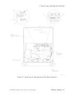
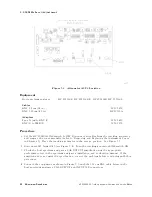
12.
Set
the
tracking
generator
LINE
switch
to
OFF
.
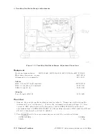
Remove
the
top
shield
from
the
A3
interface
assembly
.
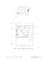
See
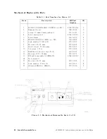
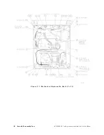
Figure
5-4.
The
bottom
shield
should
remain
in
position.
See
Figure
5-3 .
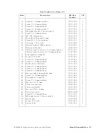
Locate
A3U4
and
note
the
HP
part
number
(0955-0311,
for
example)
or
the
manufacturer's
part
number
(MA
T-4,
for
example).
Refer
to
T
able
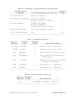
5-5
to
determine
the
current
attenuation
value
of
A3U4.
Record
the
value
below
.
Current
attenuation
value:
dB
HP
85640A
RF
T
racking
Generator
Operation
and
Service
Manual
Adjustment
Procedures
5-9
Summary of Contents for 85640A
Page 2: ...HP 85640A RF Tracking Generator Operation and Service Manual ABCDE Printed in USA ...
Page 111: ......
Page 169: ......

