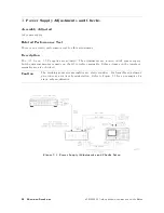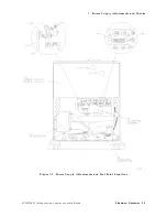
3.
P
ower
Level
A
djustments
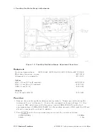
Note
The
OUTPUT
LEVEL
vernier
is
prone
to
parallax
error
.
T
o
minimize
parallax
when
setting
the
knob
,
view
the
pointer
and
the
scale
marking
directly
from
the
front
of
the
instrument
panel.
The
ridges
on
the
knob
are
also
useful
for
properly
aligning
the
pointer
with
the
scale
marking.
4.
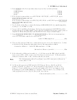
Set
the
DVM
controls
as
follows:
FUNCTION
.
.
.
.
.
.
.
.
.
.
.
.
.
.
.
.
.
.
.
.
.
.
.
.
.
.
.
.
.
.
.
.
.
.
.
.
.
.
.
.
.
.
.
.
.
.
.
.
.
.
.
.
.
.
.
.
DC
V
OL
TS
RANGE
.
.
.
.
.
.
.
.
.
.
.
.
.
.
.
.
.
.
.
.
.
.
.
.
.
.
.
.
.
.
.
.
.
.
.
.
.
.
.
.
.
.
.
.
.
.
.
.
.
.
.
.
.
.
.
.
.
.
.
.
.
.
.
.
10
V
5.
If
the
DVM
reads
+2.5
V
60.1
V
,
continue
at
step
8.
Otherwise
,
continue
to
step
6.
6.
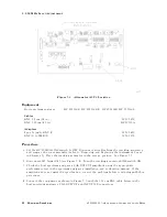
Loosen
the
set-screws
that
secure
the
OUTPUT
LEVEL
vernier
knob
to
the
vernier
control
shaft.
Remove
the
vernier
knob
.
7.
A
djust
the
shaft
for
a
DVM
reading
of
+2.5
V
60.1
V
.
Without
moving
the
position
of
the
control
shaft,
replace
the
vernier
control
knob
with
the
pointer
set
to
04
dBm.
Repeat
step
5.
8.
Press
4
PRESET
5
on
the
host
spectrum
analyzer
and
set
the
controls
as
follows:
CENTER
FREQ
.
.
.
.
.
.
.
.
.
.
.
.
.
.
.
.
.
.
.
.
.
.
.
.
.
.
.
.
.
.
.
.
.
.
.
.
.
.
.
.
.
.
.
.
.
.
.
.
.
.
.
.
.
300
MHz
SP
AN
.
.
.
.
.
.
.
.
.
.
.
.
.
.
.
.
.
.
.
.
.
.
.
.
.
.
.
.
.
.
.
.
.
.
.
.
.
.
.
.
.
.
.
.
.
.
.
.
.
.
.
.
.
.
.
.
.
.
.
.
.
.
.
.
.
.
.
0
Hz
RES
BW
.
.
.
.
.
.
.
.
.
.
.
.
.
.
.
.
.
.
.
.
.
.
.
.
.
.
.
.
.
.
.
.
.
.
.
.
.
.
.
.
.
.
.
.
.
.
.
.
.
.
.
.
.
.
.
.
.
.
.
.
.
300
Hz
TRIG
.
.
.
.
.
.
.
.
.
.
.
.
.
.
.
.
.
.
.
.
.
.
.
.
.
.
.
.
.
.
.
.
.
.
.
.
.
.
.
.
.
.
.
.
.
.
.
.
.
.
.
.
.
.
.
.
.
.
.
.
.
.
.
SINGLE
9.
If
the
host
spectrum
analyzer
an
HP
8561A,
HP
8562A,
or
HP
8562B
,
press
4
SWEEP
5
NNNNNNNNNNNNNNNNNNNNNNNNNNNNNNNNNNNNNNNNNNNNNNN
REAR
PNL
OUTPUT
NNNNNNNNNNNNNNNNNNNNNNNNNNNNNNNNNNNNNNNNNNNN
.5
V/GHz
(FAV)
.
If
the
host
spectrum
analyzer
is
an
HP
8560A/E,
HP
8561B/E,
or
HP
8563A/E,
press
4
AUX
CTRL
5
N
NNNNNNNNNNNNNNNNNNNNNNNNNNNNNNN
REAR
PANEL
NNNNNNNNNNNNNNNNNNNNNNNNNNNNNNNNNNNNNNNNNNNNNNN
0.5
V/GHz
(FAV)
.
10.
A
djust
TRA
CKING
ADJUST
to
display
a
maximum
signal
level
on
the
host
spectrum
analyzer
screen.
11.
Zero
and
calibrate
the
measuring
receiver
and
power
sensor
.
Enter
the
power
sensor's
300
MHz
Cal
F
actor
into
the
measuring
receiver
.
12.
Disconnect
the
Type
N
cable
from
the
tracking
generator
RF
OUTPUT
and
connect
the
power
sensor
to
the
RF
OUTPUT
.
13.
Set
the
OUTPUT
LEVEL
vernier
to
010
dBm.
A
djust
A3R3
L
VL
OFFSET
for
a
020
dBm
60.2
dB
reading
on
the
measuring
receiver
.
14.
Set
the
OUTPUT
LEVEL
vernier
to
0
dBm.
A
djust
A3R4
L
VL
GAIN
for
a
010
dBm
60.2
dB
reading
on
the
measuring
receiver
.
15.
Repeat
steps
13
and
14
until
the
power
level
at
each
vernier
setting
is
within
tolerance
.
16.
Set
the
OUTPUT
LEVEL
vernier
for
a
010
dBm
60.05
dB
reading
on
the
measuring
receiver
.
17.
Set
the
host
spectrum
analyzer
4
CENTER
FREQ
5
to
2.9
GHz.
18.
Enter
the
power
sensor's
3
GHz
Cal
F
actor
into
the
measuring
receiver
.
19.
A
djust
A3R2
S+T
GAIN
for
a
010
dBm
60.2
dB
reading
on
the
measuring
receiver
.
20.
Disconnect
the
DVM
test
leads
from
A3TP4
and
A3C27.
5-14
Adjustment
Procedures
HP
85640A
RF
T
racking
Generator
Operation
and
Service
Manual
Summary of Contents for 85640A
Page 2: ...HP 85640A RF Tracking Generator Operation and Service Manual ABCDE Printed in USA ...
Page 111: ......
Page 169: ......


