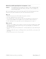
Removing
and
Replacing
the
Instrument
Cover
Caution
The
tracking
generator
assemblies
are
sensitive
to
static
.
P
erform
assembly
procedures
at
static-safe
work
stations
.
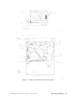
See
Figure
7-1
for
an
example
of
a
static-safe
work
station.
The
cover
assembly
is
removed
and
replaced
the
same
way
for
each
replacement
procedure
.
F
ollow
these
steps
when
performing
any
of
the
other
replacement
procedures:
Removal
1.
Remove
any
adapters
and
cables
from
the
front-panel
connectors
.
2.
Place
the
tracking
generator
on
its
front
panel.
3.
Use
a
4
mm
hex
key
to
loosen
the
four
screws
in
the
rear
bumper
feet.
(These
feet
are
secured
to
the
instrument
cover
assembly
.
It
is
not
necessary
to
remove
them
now
.)
4.
Pull
the
instrument
cover
toward
the
rear
of
the
tracking
generator
to
remove
it.
Replacement
5.
Turn
the
cover
assembly
so
the
vent
holes
are
on
the
bottom
of
the
tracking
generator
.
With
the
tracking
generator
sitting
on
its
front
panel,
slide
the
instrument
cover
assembly
onto
the
tracking
generator
.
6.
Place
the
four
screws
in
the
rear
bumper
feet.
Use
the
4
mm
hex
key
to
start
tightening
the
screws
.
7.
Alternately
tighten
the
screws
on
each
bumper
foot
to
ensure
that
the
cover
is
seated
in
the
front
frame
.
8.
T
orque
each
set
screw
to
40
or
50
inch-pounds
.
HP
85640A
RF
T
racking
Generator
Operation
and
Service
Manual
Service
Information
7-7
Summary of Contents for 85640A
Page 2: ...HP 85640A RF Tracking Generator Operation and Service Manual ABCDE Printed in USA ...
Page 111: ......
Page 169: ......

