A2
Tracking
Generator
Assembly
Replacement
Caution
The
tracking
generator
assemblies
are
static
sensitive
.
P
erform
assembly
procedures
at
static-safe
work
stations
.
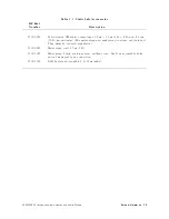
Refer
to
Figure
7-1
for
an
example
of
a
static-safe
work
station.
Removal
1.
Remove
the
instrument
cover
as
described
on
page
7-7.
2.
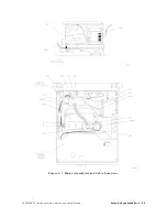
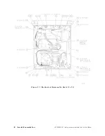
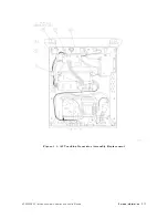
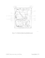
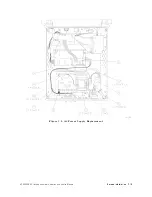
Refer
to
Figure
7-4
and
remove
the
following
ve
cable
assemblies
from
the
tracking
generator
circuitry
.
Use
caution
when
handling
the
semirigid
cables;
they
should
not
be
bent.
1
W2
from
A2J1
2
W10
from
A2J2
3
W8
from
A2J4
4
W3
from
A2J6
5
W5
from
A2J8
3.
Rotate
the
instrument
onto
its
front
panel.
Hold
the
A2
tracking
generator
as
you
remove
the
three
screws
6
that
attach
it
to
the
chassis
.
Replacement
4.
Orient
A2
with
A2J2,
A2J3,
and
A2J4
facing
toward
the
front
of
the
instrument.
5.
Attach
A2
to
the
instrument
chassis
with
the
three
screws
6
tightened
to
six
inch-pounds
.
6.
Replace
the
following
ve
cable
assemblies
.
Use
caution
when
handling
the
semirigid
cables;
they
should
not
be
bent.
1
W2
to
A2J1
2
W10
to
A2J2
3
W8
to
A2J4
4
W3
to
A2J6
5
W5
to
A2J8
7.
Tighten
the
semirigid
cable
assemblies
to
eight
inch-pounds
.
7-10
Service
Information
HP
85640A
RF
T
racking
Generator
Operation
and
Service
Manual
Summary of Contents for 85640A
Page 2: ...HP 85640A RF Tracking Generator Operation and Service Manual ABCDE Printed in USA ...
Page 111: ......
Page 169: ......

