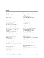
Index
0
0.5V/GHz
input,
3-4
0.5V/GHz
output,
3-6
3
300
MHz
input,
3-2
A
adjustment
procedures
600
MHz
level
adjustment,
5-7
adjustable
components,
5-3
adjustment
list
table,
5-2
adjustment
tools,
5-2
factory-selected
components,
5-3
post-repair/spec
fail
adjustment
list,
5-2
power
level
adjustment,
5-12
power
supply
adjustment,
5-3
safety
considerations,
5-1
tracking
oscillator
range
adjustment,
5-15
which
adjustment
to
perform,
5-1
alc
int
ext,
3-4
assembly
replaceable
parts,
6-1{6
introduction,
6-1
major
assembly
and
cable
locations,
6-2
mechanical
replaceable
parts,
6-4
B
bandpass
lter
rejection,
3-21
blanking
input,
3-4
block
diagrams,
7-18,
7-20
C
calibration,
equipment
needed,
3-7
characteristics,
1-11{12
connections
tracking
generator/spectrum
analyzer,
3-5
E
electrostatic
discharge,
7-2
error
messages
ERR
902
B
AD
NORM,
3-18
ERR
903
A>DLMT,
3-20
SA
VELOCK
ON,
3-17
,
3-27,
3-35,
3-40
ext
alc
input,
3-4
F
atness
out
of
tolerance,
7-27
frequency
tracking
range
performance
test,
4-31
front-panel
features,
3-2
front-panel
interconnections,
3-2
G
general
information
calibration
cycle,
1-4
characteristics,
1-11
serial
numbers,
1-4
specications,
1-6
H
harmonic
spurious
outputs
performance
test,
4-16
host
spectrum
analyzers,
4-1
HP
8560A/E,
HP
8561B/E,
HP
8563A/E
reection
measurements,
3-30
transmission
measurements,
3-9
HP
8561A,
HP
8562A/B
reection
measurements,
3-37
transmission
measurements,
3-21
I
input
power,
3-4
installation
information
compatibility
with
host
spectrum
analyzer,
2-1
inspection,
2-2
power
requirements,
2-3
preparation
for
use,
2-2
sales
and
service
oces,
2-9
instrument
description,
7-18{21
L
level
atness
performance
test,
4-12
line
switch,
3-2
LO
feedthrough
amplitude
performance
test,
4-24
LO
input,
3-2
HP
85640A
RF
T
racking
Generator
Operation
and
Service
Manual
Index-1
Summary of Contents for 85640A
Page 2: ...HP 85640A RF Tracking Generator Operation and Service Manual ABCDE Printed in USA ...
Page 111: ......
Page 169: ......


