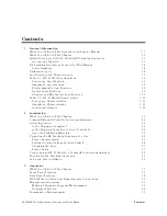
Figures
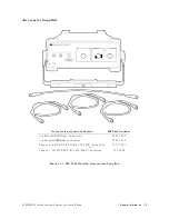
1-1.
HP
85640A
with
A
ccessories
Supplied
.
.
.
.
.
.
.
.
.
.
.
.
.
.
.
.
.
.
.
.
1-3
1-2.
An
Example
of
a
Serial
Number
Label
.
.
.
.
.
.
.
.
.
.
.
.
.
.
.
.
.
.
.
.
1-4
2-1.
V
oltage
Selection
Switch
and
Line
Fuse
Locations
.
.
.
.
.
.
.
.
.
.
.
.
.
.
2-4
2-2.
A
C
P
ower
Cables
A
vailable
.
.
.
.
.
.
.
.
.
.
.
.
.
.
.
.
.
.
.
.
.
.
.
.
.
2-6
2-3.
Front-P
anel
Cable
Connections
.
.
.
.
.
.
.
.
.
.
.
.
.
.
.
.
.
.
.
.
.
.
.
2-7
2-4.
Rear-P
anel
Cable
Connections
.
.
.
.
.
.
.
.
.
.
.
.
.
.
.
.
.
.
.
.
.
.
.
2-8
3-1.
Front-P
anel
F
eature
Overview
.
.
.
.
.
.
.
.
.
.
.
.
.
.
.
.
.
.
.
.
.
.
.
3-3
3-2.
HP
85640A
Rear-P
anel
F
eature
Overview
.
.
.
.
.
.
.
.
.
.
.
.
.
.
.
.
.
.
3-4
3-3.
Tracking
Generator-to-Host
Analyzer
Front-P
anel
Connections
.
.
.
.
.
.
.
.
3-5
3-4.
Tracking
Generator-to-Host
Analyzer
Rear-P
anel
Connections
.
.
.
.
.
.
.
.
.
3-6
3-5.
Host
Spectrum
Analyzer
and
Tracking
Generator
System
Block
Diagram
.
.
.
.
3-7
3-6.
Tracking
Generator
P
ower
over
Specied
Frequency
Range
.
.
.
.
.
.
.
.
.
.
3-10
3-7.
Display
of
DUT
Response
.
.
.
.
.
.
.
.
.
.
.
.
.
.
.
.
.
.
.
.
.
.
.
.
.
.
3-10
3-8.
System
Setup
for
Transmission
Measurement
.
.
.
.
.
.
.
.
.
.
.
.
.
.
.
.
3-11
3-9.
F
aster
Sweep
Times
in
Stimulus-Response
A
uto-Coupled
Mode
.
.
.
.
.
.
.
.
3-12
3-10.
A
djusting
the
Spectrum
Analyzer
for
Measurement
Requirements
.
.
.
.
.
.
.
3-12
3-11.
Decrease
Resolution
Bandwidth
to
Improve
Sensitivity
.
.
.
.
.
.
.
.
.
.
.
.
3-13
3-12.
Using
Tracking
A
djust
to
Compensate
for
Tracking
Error
.
.
.
.
.
.
.
.
.
.
.
3-13
3-13.
Tracking
Error
.
.
.
.
.
.
.
.
.
.
.
.
.
.
.
.
.
.
.
.
.
.
.
.
.
.
.
.
.
.
.
3-14
3-14.
Guided
Calibration
Prompt
.
.
.
.
.
.
.
.
.
.
.
.
.
.
.
.
.
.
.
.
.
.
.
.
.
3-15
3-15.
Thru
Connected
for
Guided
Calibration
Routines
.
.
.
.
.
.
.
.
.
.
.
.
.
.
.
3-16
3-16.
Display
of
Thru-Reference
Trace
in
Trace
B
.
.
.
.
.
.
.
.
.
.
.
.
.
.
.
.
.
3-17
3-17.
Normalized
Trace
.
.
.
.
.
.
.
.
.
.
.
.
.
.
.
.
.
.
.
.
.
.
.
.
.
.
.
.
.
3-18
3-18.
Measuring
Rejection
Range
with
Delta
Markers
.
.
.
.
.
.
.
.
.
.
.
.
.
.
.
3-18
3-19.
NNNNNNNNNNNNNNNNNNNNNNNNNNNNNNNNNNNNNN
NORM
REF
LVL
A
djusts
the
Trace
and
Retains
Analyzer
Settings
.
.
.
.
.
.
.
3-19
3-20.
NNNNNNNNNNNNNNNNNNNNNNNNNNNNN
RANGE
LVL
Increases
Dynamic
Measurement
Range
.
.
.
.
.
.
.
.
.
.
.
.
.
3-19
3-21.
Tracking
Generator
P
ower
over
Specied
Frequency
Range
.
.
.
.
.
.
.
.
.
.
3-21
3-22.
System
Setup
for
Transmission
Measurement
.
.
.
.
.
.
.
.
.
.
.
.
.
.
.
.
3-22
3-23.
Display
of
DUT
Response
.
.
.
.
.
.
.
.
.
.
.
.
.
.
.
.
.
.
.
.
.
.
.
.
.
.
3-22
3-24.
A
djusting
the
Spectrum
Analyzer
for
Measurement
Requirements
.
.
.
.
.
.
.
3-23
3-25.
Decrease
Resolution
Bandwidth
to
Improve
Sensitivity
.
.
.
.
.
.
.
.
.
.
.
.
3-24
3-26.
Using
TRA
CKING
ADJUST
to
Compensate
for
Tracking
Error
.
.
.
.
.
.
.
.
.
3-24
3-27.
Tracking
Error
.
.
.
.
.
.
.
.
.
.
.
.
.
.
.
.
.
.
.
.
.
.
.
.
.
.
.
.
.
.
.
3-25
3-28.
Thru
Connected
for
Calibration
Routine
.
.
.
.
.
.
.
.
.
.
.
.
.
.
.
.
.
.
.
3-26
3-29.
Display
of
Thru-Reference
Trace
in
Trace
B
.
.
.
.
.
.
.
.
.
.
.
.
.
.
.
.
.
3-27
3-30.
Normalized
Trace
.
.
.
.
.
.
.
.
.
.
.
.
.
.
.
.
.
.
.
.
.
.
.
.
.
.
.
.
.
3-28
3-31.
Measuring
Rejection
Range
with
Delta
Markers
.
.
.
.
.
.
.
.
.
.
.
.
.
.
.
3-28
3-32.
Increased
Dynamic
Measurement
Range
.
.
.
.
.
.
.
.
.
.
.
.
.
.
.
.
.
.
.
3-29
3-33.
System
Setup
for
a
Reection
Measurement
.
.
.
.
.
.
.
.
.
.
.
.
.
.
.
.
.
3-31
3-34.
Display
with
System
Congured
for
a
Reection
Measurement
.
.
.
.
.
.
.
.
3-31
3-35.
Spectrum
Analyzer
Display
of
Bandpass
Filter
Region
.
.
.
.
.
.
.
.
.
.
.
.
3-32
3-36.
On-Screen
Prompts
to
Connect
an
Open
.
.
.
.
.
.
.
.
.
.
.
.
.
.
.
.
.
.
.
3-33
3-37.
Connect
the
Open
.
.
.
.
.
.
.
.
.
.
.
.
.
.
.
.
.
.
.
.
.
.
.
.
.
.
.
.
.
3-33
3-38.
On-Screen
Prompts
to
Connect
an
Short
.
.
.
.
.
.
.
.
.
.
.
.
.
.
.
.
.
.
.
3-34
3-39.
Connect
the
Short
.
.
.
.
.
.
.
.
.
.
.
.
.
.
.
.
.
.
.
.
.
.
.
.
.
.
.
.
.
3-34
Contents-4
HP
85640A
RF
T
racking
Generator
Operation
and
Service
Manual
Summary of Contents for 85640A
Page 2: ...HP 85640A RF Tracking Generator Operation and Service Manual ABCDE Printed in USA ...
Page 111: ......
Page 169: ......

