


Chapter 4
Verifying and Booting Superdome
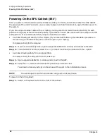
Powering On the SPU Cabinet (48 V)
82
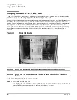
Powering On the SPU Cabinet (48 V)
After you power on the Guardian Service Processor (GSP) (+5 V HKP), and check whether the GSP detects
the presence of the UGUY and cells, you are ready to power up the SPU cabinet, or, apply the 48 V power to
the system.
If you are using a crossover cable with your laptop, you may want to review SPU cabinet activity for each
partition configured, as the SPU cabinet powers up and boots. You can open windows for the complex and for
each partition. It is recommended that you open at least two windows:
•
A window showing all activity in the complex. (If you have been following the installation procedure in
this manual, you should already have a window open on your laptop.)
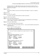
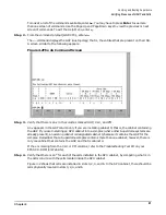
To display activity for the complex:
Step 1. If you have not already done so, open a separate Reflection 1 window and connect to the GSP.
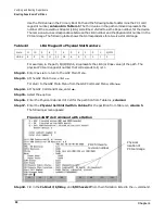
Step 2. From the GSP Main Menu, select the
VFP
(Virtual Front Panel) command with the
s
option.
•
A window showing activity for a single partition.
To display activity for each partition as it powers up:
Step 1. Open a separate Reflection 1 window and connect to the GSP.
Step 2. Select the
VFP
command and choose the partition you want to view.
You should not see any activity on the screen at this point in the installation process.
NOTE
You cannot open more than one window using a serial display device.
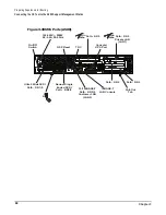
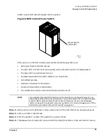
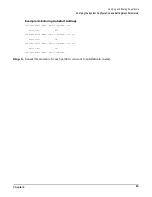
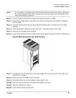
To power on the SPU cabinet:
Step 1. Switch on the power switch at the front of the cabinet.
Summary of Contents for 9000 Superdome
Page 8: ...Contents 8 ...
Page 9: ...9 Preface ...
Page 21: ...21 IEC 60417 IEC 335 1 ISO 3864 IEC 617 2 International Symbols ...
Page 22: ...22 Figure 9 Superdome Declaration of Conformity Page 1 ...
Page 23: ...23 Figure 10 Superdome Declaration of Conformity Page 2 ...
Page 24: ...24 ...
Page 32: ...Chapter 1 Introduction Installation Warranty 8 ...
Page 130: ...Chapter 4 Verifying and Booting Superdome Enabling iCOD 106 ...
Page 172: ...Appendix A hp Server rx2600 Support Management Station Configuring the SMS 148 ...
Page 184: ...Appendix C Superdome LAN Interconnect Diagram 160 ...
Page 193: ...Appendix F 169 F A180 Support Management Station ...
Page 230: ...Appendix G Connecting Multiple SPU Cabinets Connecting Cables 206 ...
Page 256: ...Appendix H JUST Exploration Tool Error Conditions 232 ...