


Chapter 4
Verifying and Booting Superdome
Performing a Visual Inspection and Completing the Installation
101
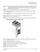
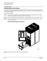
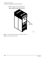
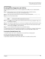
1. Hook the flange at the lower corners of the EMI panel into the holes on the SPU cabinet.
Figure 4-9Front EMI Panel Flange and SPU Cabinet Holes
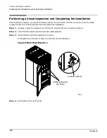
2. Position the panel at the top lip and lift the panel up while pushing the bottom into position.
You may have to compress the EMI gasket to get the panel to seat properly.
60IN054A
8/9/00
See Detail
Flange
Hole
Summary of Contents for 9000 Superdome
Page 8: ...Contents 8 ...
Page 9: ...9 Preface ...
Page 21: ...21 IEC 60417 IEC 335 1 ISO 3864 IEC 617 2 International Symbols ...
Page 22: ...22 Figure 9 Superdome Declaration of Conformity Page 1 ...
Page 23: ...23 Figure 10 Superdome Declaration of Conformity Page 2 ...
Page 24: ...24 ...
Page 32: ...Chapter 1 Introduction Installation Warranty 8 ...
Page 130: ...Chapter 4 Verifying and Booting Superdome Enabling iCOD 106 ...
Page 172: ...Appendix A hp Server rx2600 Support Management Station Configuring the SMS 148 ...
Page 184: ...Appendix C Superdome LAN Interconnect Diagram 160 ...
Page 193: ...Appendix F 169 F A180 Support Management Station ...
Page 230: ...Appendix G Connecting Multiple SPU Cabinets Connecting Cables 206 ...
Page 256: ...Appendix H JUST Exploration Tool Error Conditions 232 ...


