


Appendix A
hp Server rx2600 Support Management Station
Installing the hp Server rx2600 SMS
134
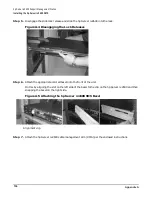
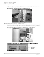
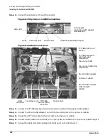
Step 5. Disengage the slide lock release and slide the hp Server rx2600 into the rack.
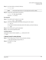
Figure A-4 Disengaging the Lock Releases
Step 6. Attach the appropriate colored bezel onto the front of the unit.
Do this by aligning the slot on the left side of the bezel to the clip on the hp Server rx2600 and then
snapping the bezel on the right side.
Figure A-5 Attaching the hp Server rx2600 SMS Bezel
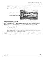
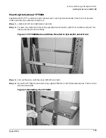
Step 7. Attach the hp Server rx2600 cable management arm (CMA) per the enclosed instructions.
Alignment clip
Summary of Contents for 9000 Superdome
Page 8: ...Contents 8 ...
Page 9: ...9 Preface ...
Page 21: ...21 IEC 60417 IEC 335 1 ISO 3864 IEC 617 2 International Symbols ...
Page 22: ...22 Figure 9 Superdome Declaration of Conformity Page 1 ...
Page 23: ...23 Figure 10 Superdome Declaration of Conformity Page 2 ...
Page 24: ...24 ...
Page 32: ...Chapter 1 Introduction Installation Warranty 8 ...
Page 130: ...Chapter 4 Verifying and Booting Superdome Enabling iCOD 106 ...
Page 172: ...Appendix A hp Server rx2600 Support Management Station Configuring the SMS 148 ...
Page 184: ...Appendix C Superdome LAN Interconnect Diagram 160 ...
Page 193: ...Appendix F 169 F A180 Support Management Station ...
Page 230: ...Appendix G Connecting Multiple SPU Cabinets Connecting Cables 206 ...
Page 256: ...Appendix H JUST Exploration Tool Error Conditions 232 ...


