


Appendix B
Installation Checklist
Using the Checklist
154
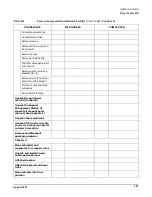
Install front door assembly
Connect control panel cable
Attach front blower bezel
Attach back blower bezel
Install PDCA
Check PDCA test points
Remove EMI panels
Set up CE tool and connect to
Local RS-232 port on GSP
Power on Circuit Breakers
(Housekeeping)
Check power to BPSs
Log in to GSP
Set private and customer LAN
IP addresses on GSP
Connect customer console
Set up network on customer
console
Connect CE tool to SMS using
9-pin to 25-pin serial cable
Connect SMS for LAN and
console access
Set up SMS for private
LAN access
Set up SMS for customer
LAN access
Set up SMS for LAN
console access
Power on and boot the SMS
Set private and customer IP
addresses on SMS
Verify LAN connection to GSP
Install and verify SMS
software
Chapter 4
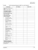
Table B-1
Factory-Integrated Installation Checklist
(Continued)
(Continued)
PROCEDURE
IN-PROCESS
COMPLETED
Summary of Contents for 9000 Superdome
Page 8: ...Contents 8 ...
Page 9: ...9 Preface ...
Page 21: ...21 IEC 60417 IEC 335 1 ISO 3864 IEC 617 2 International Symbols ...
Page 22: ...22 Figure 9 Superdome Declaration of Conformity Page 1 ...
Page 23: ...23 Figure 10 Superdome Declaration of Conformity Page 2 ...
Page 24: ...24 ...
Page 32: ...Chapter 1 Introduction Installation Warranty 8 ...
Page 130: ...Chapter 4 Verifying and Booting Superdome Enabling iCOD 106 ...
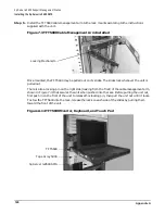
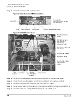
Page 172: ...Appendix A hp Server rx2600 Support Management Station Configuring the SMS 148 ...
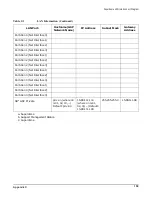
Page 184: ...Appendix C Superdome LAN Interconnect Diagram 160 ...
Page 193: ...Appendix F 169 F A180 Support Management Station ...
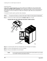
Page 230: ...Appendix G Connecting Multiple SPU Cabinets Connecting Cables 206 ...
Page 256: ...Appendix H JUST Exploration Tool Error Conditions 232 ...


