


Appendix E
Accessing the GSP Using a Modem
166
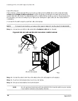
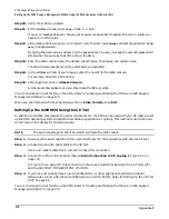
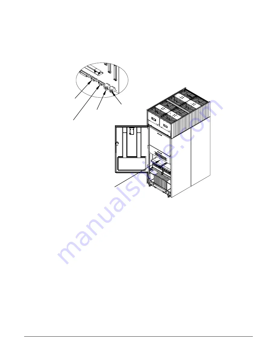
Step 1. At the site of the SPU cabinet, connect one end of a modem cable to the Remote RS-232 port on the
GSP.
Figure E-1RJ-45 LAN and RS-232 Connectors in SPU Cabinet
Step 2. Connect the other end of the RS-232 cable to the modem.
Step 3. Connect a dedicated phone (data) line to the modem.
Step 4. Set modem switches as specified in the modem documentation.
60IN050A
9/8/00
LAN and
RS-232 Connectors
Local
RS232
Remote
RS232
LAN
Customer
LAN
Private
Summary of Contents for 9000 Superdome
Page 8: ...Contents 8 ...
Page 9: ...9 Preface ...
Page 21: ...21 IEC 60417 IEC 335 1 ISO 3864 IEC 617 2 International Symbols ...
Page 22: ...22 Figure 9 Superdome Declaration of Conformity Page 1 ...
Page 23: ...23 Figure 10 Superdome Declaration of Conformity Page 2 ...
Page 24: ...24 ...
Page 32: ...Chapter 1 Introduction Installation Warranty 8 ...
Page 130: ...Chapter 4 Verifying and Booting Superdome Enabling iCOD 106 ...
Page 172: ...Appendix A hp Server rx2600 Support Management Station Configuring the SMS 148 ...
Page 184: ...Appendix C Superdome LAN Interconnect Diagram 160 ...
Page 193: ...Appendix F 169 F A180 Support Management Station ...
Page 230: ...Appendix G Connecting Multiple SPU Cabinets Connecting Cables 206 ...
Page 256: ...Appendix H JUST Exploration Tool Error Conditions 232 ...


