


Appendix F
A180 Support Management Station
Setting Up the A180 Support Management Station Using the Web Console or the Serial Port
174
Step 10. Verify that JAVA is enabled.
Step 11. In the address window, enter
http://192.0.0.192
.
If an error message appears, change your browser configuration to satisfy the error. Usually you
have to turn off proxies.
Step 12. At the Web console screen on your browser, enter the user name
hduser
and set the password as
hd
user
(hd<space>user).
By typing the username as hduser and the password as hd user, you keep the username/password
combination the same as that of the OS on the SMS.
Step 13. Enter the Web console name, IP address, subnet mask, IP gateway, and system name.
The Web console reboots using the parameters you specified.
Step 14. In the address window of your browser, enter the new IP for the Web console.
For example, http://111.222.333.444.
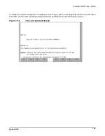
Step 15. After logging in, click on Access Console.
A console window appears and you should see the BCH prompt.
You are now ready to boot the OS on the SMS. Refer to “Loading and Booting the OS on an A180 Support
Management Station” on page 175.
When you are finished with the Web console, click on Close Console, then Exit.
Setting Up the A180 SMS Using the CE Tool
In addition to the Web console port, the serial console port on the SMS can be used with your CE laptop to set
up the SMS operating system and additional software applications. Typically, this method is used when you
do not have an IP address for the Web console.
NOTE
The serial console port cannot be used to configure the Web console.
Step 1. Disconnect the serial cable from the Local RS-232 port on the Superdome GSP and the CE tool.
Step 2. Connect one end of a serial cable to the CE tool.
Use a null modem cable (9-pin to 9-pin) to make this connection.
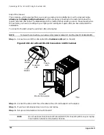
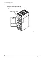
Step 3. Connect the other end to the port labeled Serial Connection to CE Laptop in Figure F-2 on
In Figure F-3 on page 173, this connection is shown as a dotted line between the CE TOOL (PC)
and the SUPPORT MANAGEMENT STATION.
Step 4. If you have not already done so, set up Reflection 1, or other appropriate terminal emulator
software to connect with the port at 9600, 8/none, and HP-TERM. Refer to “Setting Up the CE Tool
(PC)” on page 56.
You are now ready to boot the OS on the SMS. Refer to “Loading and Booting the OS on an A180 Support
Management Station” on page 175.
Summary of Contents for 9000 Superdome
Page 8: ...Contents 8 ...
Page 9: ...9 Preface ...
Page 21: ...21 IEC 60417 IEC 335 1 ISO 3864 IEC 617 2 International Symbols ...
Page 22: ...22 Figure 9 Superdome Declaration of Conformity Page 1 ...
Page 23: ...23 Figure 10 Superdome Declaration of Conformity Page 2 ...
Page 24: ...24 ...
Page 32: ...Chapter 1 Introduction Installation Warranty 8 ...
Page 130: ...Chapter 4 Verifying and Booting Superdome Enabling iCOD 106 ...
Page 172: ...Appendix A hp Server rx2600 Support Management Station Configuring the SMS 148 ...
Page 184: ...Appendix C Superdome LAN Interconnect Diagram 160 ...
Page 193: ...Appendix F 169 F A180 Support Management Station ...
Page 230: ...Appendix G Connecting Multiple SPU Cabinets Connecting Cables 206 ...
Page 256: ...Appendix H JUST Exploration Tool Error Conditions 232 ...


