


Appendix G
Connecting Multiple SPU Cabinets
180
NOTE
These instructions assume that you have unpacked both SPU cabinets using the unpacking
instructions that came with the cabinets. Refer to “Unpacking the Superdome SPU Cabinet” on
page 16.
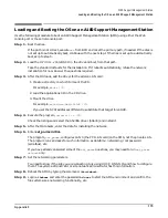
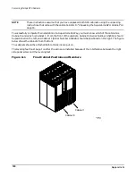
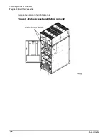
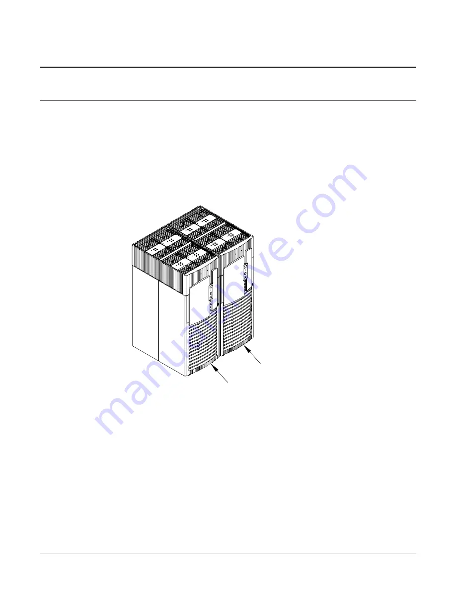
To successfully complete the installation of a Superdome 64 Way, you must know which of the cabinets is
Cabinet 0 and which is Cabinet 1. From the front of the cabinets, Cabinet 0 (Serial Number A5201A) should
be positioned on the left, and Cabinet 1 (Serial Number A5202A) should be positioned on the right. The figure
below shows the cabinets from the front.
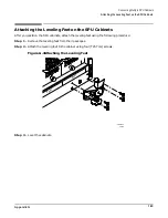
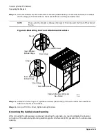
The cabinets should be attached before the skins are put on.
The leveling feet must be put on after the skins are installed because of the interference between the right
side panel screw and the leveling feet.
Figure G-1
Final Cabinet Positions and Numbers
60IN022A
7/21/00
Cabinet 0
Cabinet 1
Summary of Contents for 9000 Superdome
Page 8: ...Contents 8 ...
Page 9: ...9 Preface ...
Page 21: ...21 IEC 60417 IEC 335 1 ISO 3864 IEC 617 2 International Symbols ...
Page 22: ...22 Figure 9 Superdome Declaration of Conformity Page 1 ...
Page 23: ...23 Figure 10 Superdome Declaration of Conformity Page 2 ...
Page 24: ...24 ...
Page 32: ...Chapter 1 Introduction Installation Warranty 8 ...
Page 130: ...Chapter 4 Verifying and Booting Superdome Enabling iCOD 106 ...
Page 172: ...Appendix A hp Server rx2600 Support Management Station Configuring the SMS 148 ...
Page 184: ...Appendix C Superdome LAN Interconnect Diagram 160 ...
Page 193: ...Appendix F 169 F A180 Support Management Station ...
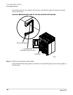
Page 230: ...Appendix G Connecting Multiple SPU Cabinets Connecting Cables 206 ...
Page 256: ...Appendix H JUST Exploration Tool Error Conditions 232 ...


