


Appendix G
Connecting Multiple SPU Cabinets
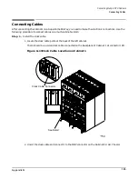
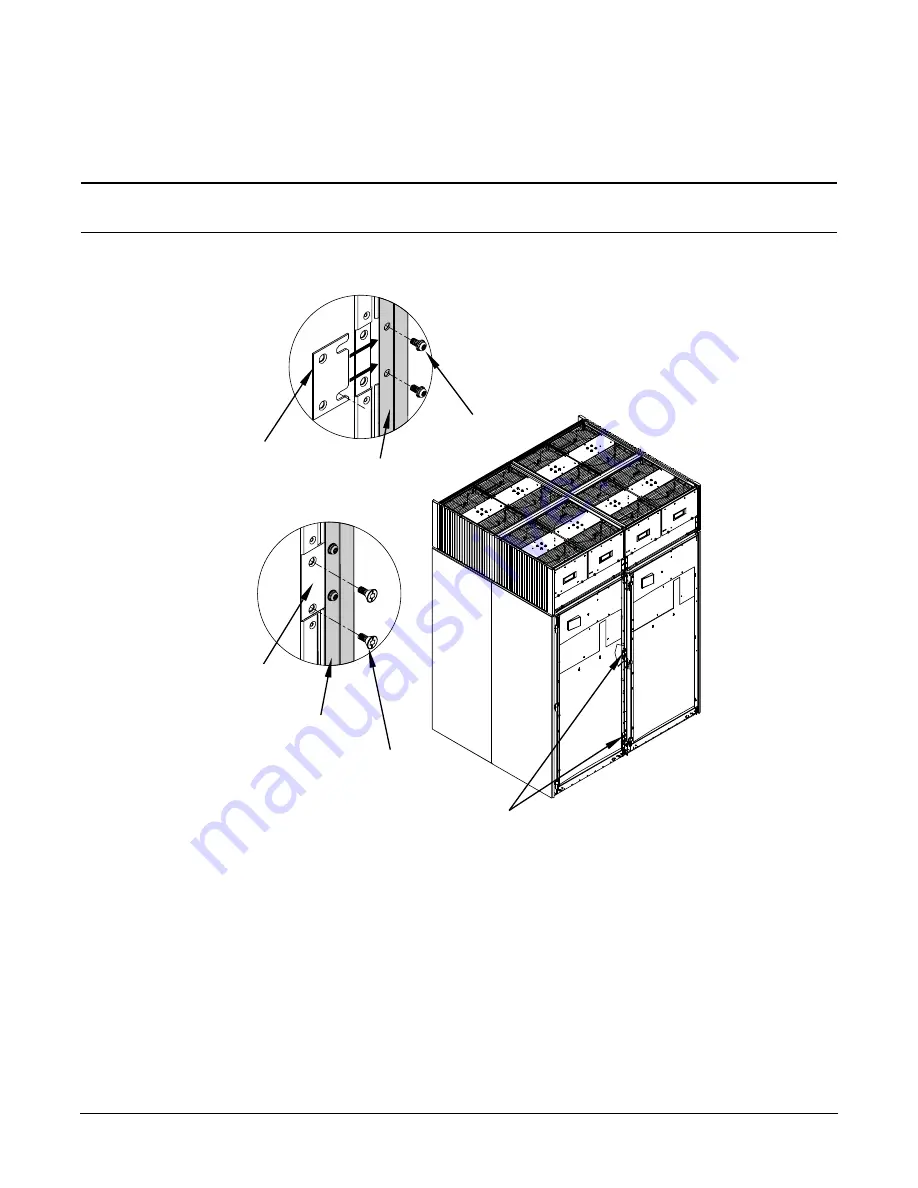
Connecting the Cabinets
190
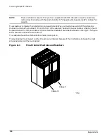
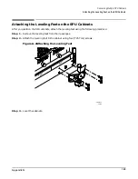
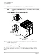
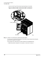
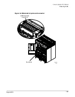
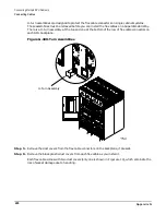
Step 2. Slide the slotted side of the attachment bracket (A5201-00241) into the slots between the cabinet
and the hinge, so that the slots on the brackets fit around the pan head screws.
NOTE
Make sure the bracket is between the back of the hinge and the front of the cabinet
frame.
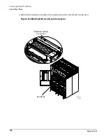
Figure G-8Installing the Front Attachment Brackets
Step 3. Attach the remaining four (4) flathead screws (0515-3210) provided to install the brackets to
Cabinet 0, two for each bracket.
Step 4. Using a T30 Torx driver, tighten all eight screws.
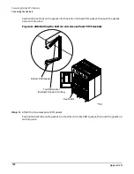
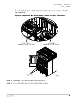
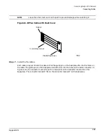
Grooming the Cable Access Opening
After removing the cable access panels and connecting the cabinets, you need to complete the physical
connection of the cabinets by attaching electromagnetic interference (EMI) gaskets into the cable access
opening.
12/5/00
60IN086A
Cabinet Attachment Bracket
See Detail
Insert Bracket
Pan Head Screws
Flat Head Screws
Behind Hinge
Door Hinge
Insert Bracket
Door Hinge
Behind Hinge
Step 1
Step 2
Summary of Contents for 9000 Superdome
Page 8: ...Contents 8 ...
Page 9: ...9 Preface ...
Page 21: ...21 IEC 60417 IEC 335 1 ISO 3864 IEC 617 2 International Symbols ...
Page 22: ...22 Figure 9 Superdome Declaration of Conformity Page 1 ...
Page 23: ...23 Figure 10 Superdome Declaration of Conformity Page 2 ...
Page 24: ...24 ...
Page 32: ...Chapter 1 Introduction Installation Warranty 8 ...
Page 130: ...Chapter 4 Verifying and Booting Superdome Enabling iCOD 106 ...
Page 172: ...Appendix A hp Server rx2600 Support Management Station Configuring the SMS 148 ...
Page 184: ...Appendix C Superdome LAN Interconnect Diagram 160 ...
Page 193: ...Appendix F 169 F A180 Support Management Station ...
Page 230: ...Appendix G Connecting Multiple SPU Cabinets Connecting Cables 206 ...
Page 256: ...Appendix H JUST Exploration Tool Error Conditions 232 ...


