


Appendix G
Connecting Multiple SPU Cabinets
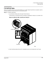
Connecting Cables
201
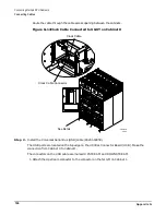
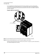
NOTE
Leave the other dust cover on the part to prevent damage while installing it.
Figure G-19Flex Cable with Dust Cover
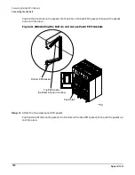
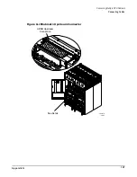
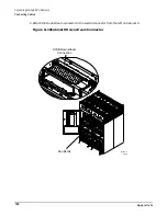
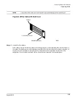
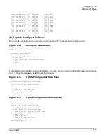
Step 7. Install the flex cables.
Each cable is keyed. Orient the cable so that the guide pin on the backplane fits into the holes on
the cable. The guide pins on the backplane connector fits into the holes on the cable connector. In
Figure G-20, the connector marked N (with no holes) fits on the connector marked N on the
backplane. The connector marked P fits on the connector marked P on the backplane.
60IN088A
01/25/01
Socket
5 inch Flex Circuit
Plastic Dustcover
Summary of Contents for 9000 Superdome
Page 8: ...Contents 8 ...
Page 9: ...9 Preface ...
Page 21: ...21 IEC 60417 IEC 335 1 ISO 3864 IEC 617 2 International Symbols ...
Page 22: ...22 Figure 9 Superdome Declaration of Conformity Page 1 ...
Page 23: ...23 Figure 10 Superdome Declaration of Conformity Page 2 ...
Page 24: ...24 ...
Page 32: ...Chapter 1 Introduction Installation Warranty 8 ...
Page 130: ...Chapter 4 Verifying and Booting Superdome Enabling iCOD 106 ...
Page 172: ...Appendix A hp Server rx2600 Support Management Station Configuring the SMS 148 ...
Page 184: ...Appendix C Superdome LAN Interconnect Diagram 160 ...
Page 193: ...Appendix F 169 F A180 Support Management Station ...
Page 230: ...Appendix G Connecting Multiple SPU Cabinets Connecting Cables 206 ...
Page 256: ...Appendix H JUST Exploration Tool Error Conditions 232 ...


