


Appendix G
Connecting Multiple SPU Cabinets
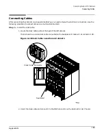
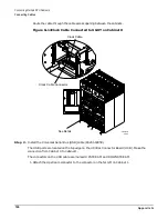
Connecting Cables
203
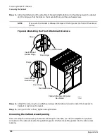
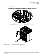
NOTE
Do not overtighten the screws.
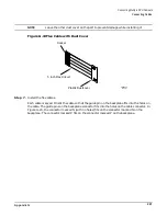
Step 2. Install the two 8-inch cables over the top and the bottom 5-inch cables.
Figure G-21 Installing 8-inch Cables
Step 3. Inspect the cables to verify that they are installed properly.
60IN070A
1/25/01
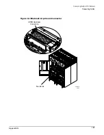
See Detail
8 inch Flex Cable
5 inch Flex Cable
Left Backplane board
Right Backplane Board
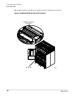
5 inch Flex Cables
L3-L1
L2-L3
L1-L2
L1-L2
L3-L1
L2-L3
L1-L2
L2-L3
L3-L1
L2-L3
L3-L1
L1-L2
Summary of Contents for 9000 Superdome
Page 8: ...Contents 8 ...
Page 9: ...9 Preface ...
Page 21: ...21 IEC 60417 IEC 335 1 ISO 3864 IEC 617 2 International Symbols ...
Page 22: ...22 Figure 9 Superdome Declaration of Conformity Page 1 ...
Page 23: ...23 Figure 10 Superdome Declaration of Conformity Page 2 ...
Page 24: ...24 ...
Page 32: ...Chapter 1 Introduction Installation Warranty 8 ...
Page 130: ...Chapter 4 Verifying and Booting Superdome Enabling iCOD 106 ...
Page 172: ...Appendix A hp Server rx2600 Support Management Station Configuring the SMS 148 ...
Page 184: ...Appendix C Superdome LAN Interconnect Diagram 160 ...
Page 193: ...Appendix F 169 F A180 Support Management Station ...
Page 230: ...Appendix G Connecting Multiple SPU Cabinets Connecting Cables 206 ...
Page 256: ...Appendix H JUST Exploration Tool Error Conditions 232 ...


