


Chapter 3
Preparing Superdome for Booting
Unpacking and Installing the Blower Housings and Blowers
34
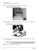
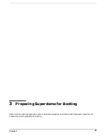
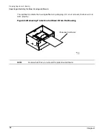
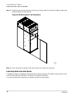
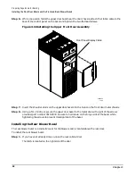
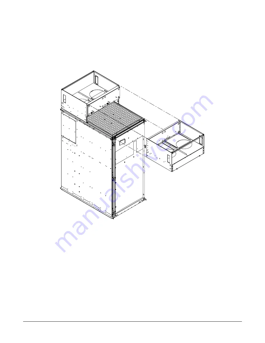
Step 4. Using the handles on the housing labeled Blower 0 Blower 1, part number A5201-62030, align
the edge of the housing over the edge at the top front of the SPU cabinet, and slide it into place
until the connectors at the back of each housing are fully mated; then tighten the thumbscrews at
the front of the housing.
Figure 3-4Installing the Front Blower Housing
Step 5. Unpack each of the four blowers.
10/27/00
60IN003A
Summary of Contents for 9000 Superdome
Page 8: ...Contents 8 ...
Page 9: ...9 Preface ...
Page 21: ...21 IEC 60417 IEC 335 1 ISO 3864 IEC 617 2 International Symbols ...
Page 22: ...22 Figure 9 Superdome Declaration of Conformity Page 1 ...
Page 23: ...23 Figure 10 Superdome Declaration of Conformity Page 2 ...
Page 24: ...24 ...
Page 32: ...Chapter 1 Introduction Installation Warranty 8 ...
Page 130: ...Chapter 4 Verifying and Booting Superdome Enabling iCOD 106 ...
Page 172: ...Appendix A hp Server rx2600 Support Management Station Configuring the SMS 148 ...
Page 184: ...Appendix C Superdome LAN Interconnect Diagram 160 ...
Page 193: ...Appendix F 169 F A180 Support Management Station ...
Page 230: ...Appendix G Connecting Multiple SPU Cabinets Connecting Cables 206 ...
Page 256: ...Appendix H JUST Exploration Tool Error Conditions 232 ...