


Chapter 3
Preparing Superdome for Booting
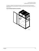
Installing and Verifying the PDCA
47
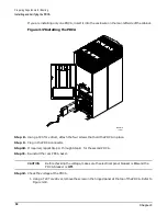
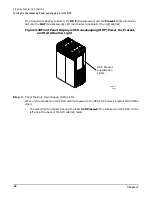
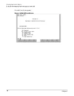
Installing and Verifying the PDCA
All Superdomes are delivered with the appropriate cable plug for Options 6 and 7. The mating receptacle
connector is not provided as with Options 4 and 5.
Check the voltages at the receptacle prior to plugging in the PDCA plug. Refer to Figure 3-15 and Figure 3-16
on page 49 for pin locations.
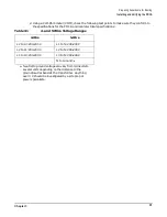
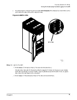
•
To verify the proper wiring for a four-wire PDCA, use a DVM to measure the voltage at the receptacle.
Voltage should read 200 - 240 Vac phase-to-phase as measured between the receptacle pins as follows: L1
to L2, L2 to L3, L1 to L3.
Summary of Contents for 9000 Superdome
Page 8: ...Contents 8 ...
Page 9: ...9 Preface ...
Page 21: ...21 IEC 60417 IEC 335 1 ISO 3864 IEC 617 2 International Symbols ...
Page 22: ...22 Figure 9 Superdome Declaration of Conformity Page 1 ...
Page 23: ...23 Figure 10 Superdome Declaration of Conformity Page 2 ...
Page 24: ...24 ...
Page 32: ...Chapter 1 Introduction Installation Warranty 8 ...
Page 130: ...Chapter 4 Verifying and Booting Superdome Enabling iCOD 106 ...
Page 172: ...Appendix A hp Server rx2600 Support Management Station Configuring the SMS 148 ...
Page 184: ...Appendix C Superdome LAN Interconnect Diagram 160 ...
Page 193: ...Appendix F 169 F A180 Support Management Station ...
Page 230: ...Appendix G Connecting Multiple SPU Cabinets Connecting Cables 206 ...
Page 256: ...Appendix H JUST Exploration Tool Error Conditions 232 ...


