


Chapter 3
Preparing Superdome for Booting
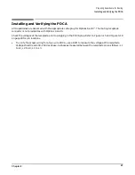
Installing and Verifying the PDCA
50
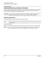
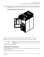
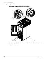
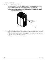
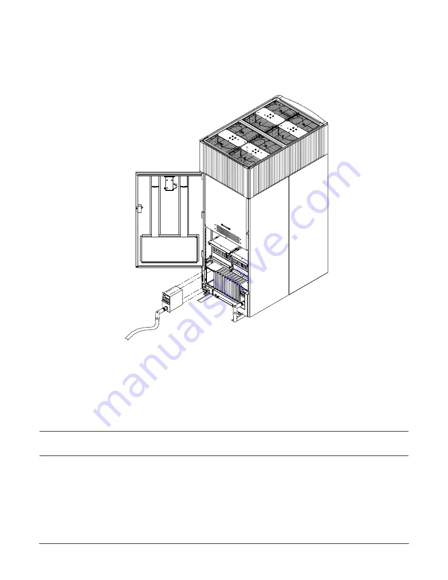
If you are installing only one PDCA, insert it into the enclosure on the rear-left side of the cabinet.
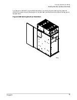
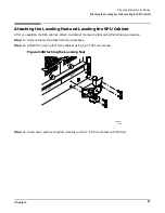
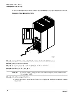
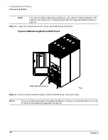
Figure 3-17Installing the PDCA
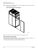
Step 8. Using a T20 Torx driver, attach the four screws that hold the PDCA in place.
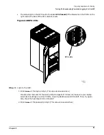
Step 9. Plug in the PDCA connector.
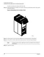
Step 10. If required, repeat Step 4. through Step 8. for the second PDCA.
Step 11. Re-install the rear PDCA bezel.
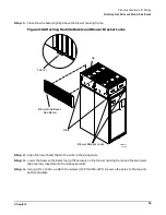
CAUTION
Before checking the voltage, make sure the electrical panel breaker is On and the
PDCA breaker is Off.
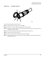
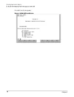
Step 12. Check the voltage at the PDCA.
1. Using a T20 Torx driver, remove the screw on the hinged panel at the top of the PDCA. Refer to
60RR027B
11/15/01
L3-L1
L1-L2
L2-L3
L2-L3
L1-L2
L3-L1
Summary of Contents for 9000 Superdome
Page 8: ...Contents 8 ...
Page 9: ...9 Preface ...
Page 21: ...21 IEC 60417 IEC 335 1 ISO 3864 IEC 617 2 International Symbols ...
Page 22: ...22 Figure 9 Superdome Declaration of Conformity Page 1 ...
Page 23: ...23 Figure 10 Superdome Declaration of Conformity Page 2 ...
Page 24: ...24 ...
Page 32: ...Chapter 1 Introduction Installation Warranty 8 ...
Page 130: ...Chapter 4 Verifying and Booting Superdome Enabling iCOD 106 ...
Page 172: ...Appendix A hp Server rx2600 Support Management Station Configuring the SMS 148 ...
Page 184: ...Appendix C Superdome LAN Interconnect Diagram 160 ...
Page 193: ...Appendix F 169 F A180 Support Management Station ...
Page 230: ...Appendix G Connecting Multiple SPU Cabinets Connecting Cables 206 ...
Page 256: ...Appendix H JUST Exploration Tool Error Conditions 232 ...


