background image

Chapter 3

Preparing Superdome for Booting

Setting the Private and Customer LAN Information on the GSP

65

To return to the GSP main menu, enter 

ma

.

To exit the GSP, enter 

x

 at the GSP main menu.

Summary of Contents for 9000 Superdome

Page 1: ...Superdome Installation Guide HP 9000 Systems Sixth Edition Manufacturing Part Number A5201 10028 60304 USA ...

Page 2: ...raph c 1 ii of the Rights in Technical Data and Computer Software clause at DFARS 252 227 7013 for DOD agencies and subparagraphs c 1 and c 2 of the Commercial Computer Software Restricted Rights clause at FAR 52 227 19 for other agencies HEWLETT PACKARD COMPANY 3000 Hanover Street Palo Alto California 94304 U S A Copyright Notices copyright 1983 2004 Hewlett Packard Company all rights reserved Re...

Page 3: ...Other Equipment 24 Unpacking the PDCA 26 Returning Equipment 28 3 Preparing Superdome for Booting Moving the Superdome System and Related Equipment to the Installation Site 30 Unpacking and Installing the Blower Housings and Blowers 31 Attaching Side Skins and Blower Side Bezels 36 Attaching the Side Skins 36 Attaching the Blower Side Bezels 38 Attaching the Leveling Feet and Leveling the SPU Cabi...

Page 4: ...SPU Cabinet 48 V 82 Verifying the System Configuration and Setting Boot Parameters 84 Setting Automatic System Restart 84 Running JUST Software 86 Booting Superdome Partitions 87 Determining and Documenting Boot Information 88 Setting Up the Boot Device 91 Booting UNIX on the Partition s 92 Installing Superdome I O Cards 94 Selecting a PCI Card Slot 94 Installing a PCI Card 94 Installing Periphera...

Page 5: ...A hp Server rx2600 Support Management Station Installing the hp Server rx2600 SMS 132 Required Tools 132 Racking the hp Server rx2600 SMS 132 Installing the Tape Array 5300A 135 Mounting the Optional TFT5600 139 Connecting the SMS Cables 141 Configuring the SMS 143 Connecting to the hp Server rx2600 Console 143 EFI Boot Paths 143 Enabling the VGA Local Console Output 143 Configuring the Operating ...

Page 6: ...d Customer IP Addresses on the Support Management Station 176 G Connecting Multiple SPU Cabinets Equipment Checklist 181 Positioning the SPU Cabinets for Connection 182 Attaching the Leveling Feet on the SPU Cabinets 183 Removing the Rear EMI Panel 184 Preparing Cabinet 1 for Connection 185 Preparing Cabinet 0 for Connection 188 Connecting the Cabinets 189 Installing the Rear Attachment Brackets 1...

Page 7: ...Contents 7 Unpacking the Support Management Station 234 Racking the Support Management Station and Peripherals 235 Connecting SCSI Cables and Setting SCSI Addresses on the Support Management Station 236 ...

Page 8: ...Contents 8 ...

Page 9: ...9 Preface ...

Page 10: ...r new SMS an hp Server rx2600 Fifth A5201 10022 November 2001 Added new PDCA options Fourth A5201 10017 August 2001 Updated for Caribe Third A5201 10014 July 2001 Added Safety and Regulatory section in preface Added no boot disk chapter Added info on lower breaker value usage pay per use and iCOD modem support Added general corrections per edits ...

Page 11: ...ngs WARNING Warnings highlight procedures or information necessary to avoid injury to personnel The warning should tell the reader exactly what will result from what actions and how to avoid them CAUTION A caution highlights procedures or information necessary to avoid damage to equipment damage to software loss of data or invalid test results NOTE A note highlights supplemental information Acrony...

Page 12: ...ed or unpacked up or down an incline of more than 15ο USA Radio Frequency Interference FCC Notice The Federal Communications Commission in CFR Part 15 has specified that the following notice be brought to the attention of the users of this product NOTE This equipment has been tested and found to comply with the limits for a Class A digital device pursuant to Part 15 of the FCC Rules These limits a...

Page 13: ...l and or industrial areas Consequently when used in a residential area or in an adjacent area thereto radio interference may be caused to radios and TV receivers etc Read the instructions for correct handling Figure 1 Japanese RFI Statement Korean RFI Statement 1 Equipment Name Model Name 2 Certification No 3 Name of Certification Recipient 4 Date of Manufacture 5 Manufacturer Nation Figure 2 Kore...

Page 14: ...ea as well as residential area European Union RFI Statement This is a Class A product In a domestic environment this product may cause radio interference in which case the user may be required to take adequate measures Canada RFI Statement This Class A digital apparatus meets all requirements of the Canadian Interference Causing Equipment Regulations Notice relative aux interférences radioélectriq...

Page 15: ...having no direct connection to earth according to IEC 60950 TT TN C and TN C S Power Systems These products should not be connected to power systems that switch open the return lead when the return lead also functions as the protective earth A separate PE ground wire must be connected to the equipment at the designated PE terminal tie point High Leakage Current WARNING High leakage current Ground ...

Page 16: ...e system against abnormal hazards Table 3 details the circuit breaker specifications WARNING Provide a disconnect device to protect against abnormal hazards Systems configured with a full complement of cells memory and I O and connected to a 5 wire source must have a maximum 60A 3 phase with neutral 4 pole circuit breaker installed as part of the building installation Systems configured with a ful...

Page 17: ... typical numbers to be about 18 less for PA8700 systems Table 4 also shows the recommended breaker sizes for 4 wire and 5 wire sources Table 4 Typical Superdome Configurations Cell Boards Memory Per Cell Board I O Chassis Modules Breaker Powera Recommended 3 pole Breaker Sizea b Recommended 4 pole Breaker Sizea c Typical Power Typical Cooling Qty GBytes Qty Watts Amps min Amps min Watts BTU HR 8 1...

Page 18: ...tem will always be wired as 240 volts phase to phase no neutral or common plus a PE ground Three phase input voltage 240VAC to the equipment is connected phase to phase Examples of 4 wire 200 volt phase to phase 208 volt phase to phase 240 volt phase to phase c An input power source supplied from a 4 pole PE 5 wire system may be wired as either 208VAC phase to phase voltage with a common plus a PE...

Page 19: ...and rating Lithium Battery Caution WARNING Observe the correct polarity when changing the lithium battery There is a danger of explosion if battery is installed incorrectly Replace only with the same or equivalent type recommended by the manufacturer Dispose of used batteries according to the manufacturer s instructions and local disposal requirements IMPORTANT Switzerland Annex 4 10 of SR 814 013...

Page 20: ... in this manual Standard for the Protection of Electronic Computer Data Processing Equipment NFPA75 National Fire Protection Association EIA Standard RS 232 C Electronic Industries Association Electrostatic Discharge Failures of Semiconductor Devices Unger B A 1981 Bell Laboratories IEC 60950 EN 60950 UL 60950 CSA 22 2 No 950 Standards for Safety of Information Technology Equipment ...

Page 21: ...21 IEC 60417 IEC 335 1 ISO 3864 IEC 617 2 International Symbols ...

Page 22: ...22 Figure 9 Superdome Declaration of Conformity Page 1 ...

Page 23: ...23 Figure 10 Superdome Declaration of Conformity Page 2 ...

Page 24: ...24 ...

Page 25: ...allation and configuration procedures for the Hewlett Packard Precision Architecture RISC PA RISC Superdome system The instructions in this guide are written for Customer Engineers CE who are experienced or inexperienced at installing Superdome systems ...

Page 26: ...ully To avoid having to undo and redo an installation step we urge you to follow the installation sequence outlined in this guide After you have done one installation you may use Appendix B to refresh your memory on the installation sequence Experienced Installers Appendix B contains a checklist that describes the procedure to install a factory integrated Superdome The factory integrated checklist...

Page 27: ...ccessfully completed HP s authorized training should perform these installation procedures Notational Conventions This section discusses notational conventions used in this book Italic In paragraph text italic identifies new and important terms and titles of documents In command syntax diagrams italic identifies variables that must be supplied by the user Bold In paragraph text bold identifies eit...

Page 28: ...t and cleaning up the installation site Accepting the Equipment The customer should oversee the arrival of the equipment including checking the inventory and moving the equipment to the final installation location The customer and the field engineer should inspect the equipment when it is unpacked and inventory the equipment with the Sales Order Packing Slip or the customer s Bill of Material It i...

Page 29: ...vision communications Installing and using the system in strict accordance with Hewlett Packard s instructions minimizes the chances that the system will cause radio or television interference However Hewlett Packard does not guarantee that the system will not interfere with radio and television reception Take these precautions Use only shielded cables Install and route the cables per the instruct...

Page 30: ...rking on or around system components Treat all assemblies components and interface connections as static sensitive When unpacking cards interfaces and other accessories that are packaged separately from the system keep the accessories in their conductive plastic bags until they are ready to be installed Before removing or replacing any components or installing any accessories in the system select ...

Page 31: ...until Field Services turns the system over to the customer Upon inspection of a received system and or during installation of the system if any parts or accessories are missing or defective they will be replaced directly from the factory via a priority process To request replacement parts contact the local Order Fulfillment group who will coordinate the replacement with the factory ...

Page 32: ...Chapter 1 Introduction Installation Warranty 8 ...

Page 33: ...Chapter 2 9 2 Unpacking and Inspecting This chapter describes what to do before unpacking the Superdome Enterprise Server and how to unpack the system itself ...

Page 34: ...Chapter 2 Unpacking and Inspecting 10 WARNING Do not attempt to move the Superdome cabinet either packed or unpacked up or down an incline of more than 15ο ...

Page 35: ...the IP addresses you need while you are unpacking the system To help you get the information you need remove the Superdome LAN Interconnect Diagram in Appendix C and have the customer fill out the table that accompanies the diagram Verifying Electrical Requirements The site should have been verified for proper grounding and electrical requirements prior to the system being shipped to the customer ...

Page 36: ...irst This box contains the Solution Information Manual and DDCAs Unpacking Instructions are in the plastic bag taped to the System Processing Unit SPU The following items are in other containers and should be checked against the packing list Power Distribution Control Assembly PDCA and power cord Two blower housings per SPU cabinet Four blowers per SPU cabinet Four side skins with related attachme...

Page 37: ...ewlett Packard shipping containers are designed to protect their contents under normal shipping conditions After the equipment arrives at the customer site carefully inspect each carton for signs of shipping damage WARNING Do not attempt to move the Superdome cabinet either packed or unpacked up or down an incline of more than 15ο ...

Page 38: ...is in an abnormal condition visually inspect the unit for any signs of damage If damage is found document the damage with photographs and contact the transport carrier immediately Figure 2 1 Tilt Indicator Normal 6 1 00 60IN009A Detail C A U T I O N R S H C I O V T KEEP UPRIGHT TENIR DEBOUT Each window must show 4 balls Balls missing The package has been tilted H an er W eg 48 T el 0 6 9 01 23 40 ...

Page 39: ...ng material If it becomes necessary to repackage the cabinet the original packing material will be needed If you decide to discard the shipping container or packaging material please dispose of them in an environmentally responsible manner recycle if possible Claims Procedures If the shipment is incomplete the equipment is damaged or it fails to meet specifications notify the nearest Hewlett Packa...

Page 40: ...9 pin Null modem cable HP Part Number F1047 80002 Serial display device A serial display device can be a device such as an HPTERM a laptop connected by a serial cable or LAN connection or any device capable of displaying text and communicating with the Guardian Service Processor GSP Unpacking the Superdome SPU Cabinet CAUTION Use three people to unpack the SPU cabinet safely It is recommended that...

Page 41: ...packaged SPU cabinet so that a clear area about three times the length of the package about 12 feet is available in front of the unit and at least two feet are available on the sides Figure 2 3Front of SPU Cabinet Container Step 2 Cut the plastic polystrap bands around the shipping container 5 31 00 60IN011A Label ...

Page 42: ...glasses These bands are under tension When cut they spring back and could cause serious eye injury Figure 2 4Cutting Polystrap Bands Step 3 Lift the cardboard corrugated top cap off of the shipping box Step 4 Remove the corrugated sleeves surrounding the cabinet Step 5 Remove the stretch wrap the front and rear top foam inserts and the four corner inserts from the cabinet 6 1 00 60IN011B Polystrap...

Page 43: ...i static bag by lifting it straight up off the cabinet and check for damage If you find damage follow the claims procedure Some damage may be repaired by replacing the damaged part If extensive damage is found it may be necessary to repack and return the entire cabinet to HP Exterior Check the cabinet exterior for signs of shipping damage Step 1 Look at the top and sides for dents warpage or scrat...

Page 44: ...npacking and Inspecting Superdome Hardware Components 20 Step 2 Check that the power supply mounting screws are in place and locked Figure 2 6Check Power Supply Mounting Screws 60IN015A 10 30 00 Power Supplies Mounting Screw Power Supply ...

Page 45: ...Components 21 Step 3 Check to see that the I O chassis mounting screws are in place and secure Figure 2 7I O Chassis Mounting Screws Interior Check all components for signs of shifting during shipment or any signs of damage 60IN018A 10 30 00 I O Chassis I O Chassis Mounting Screw ...

Page 46: ...s on the side of the pallet where the ramp slots are located Figure 2 9Removing the Mounting Brackets Step 6 On the other side of the pallet remove only the bolt on each mounting bracket that is attached to the SPU cabinet WARNING Do not remove the bolts on the mounting brackets that attach to the pallet These bolts prevent the cabinet from rolling off the back of the pallet Step 7 Insert the ramp...

Page 47: ...allel and aligned The casters on the cabinet should roll unobstructed onto the ramp Figure 2 10Positioning the Ramps WARNING The cabinet can weigh as much as 1400 lbs Three people are required to roll the cabinet off the pallet Position one person at the rear of the SPU cabinet and one person on each side 60IN014A 10 27 00 Ramps ...

Page 48: ...t When ordered with a Superdome system the Support Managements Station SMS and its peripherals come in a peripheral cabinet racked and cabled Unpack the peripheral cabinet according to the installation instructions that come with it NOTE If by special arrangement the SMS is shipped to the customer separate from a peripheral cabinet refer to Appendix I Unpacking the SMS Connecting Cables and Settin...

Page 49: ...is includes options spare parts cables and software Refer to the original purchase order if required Step 3 If optional assemblies or cards have been ordered separately make sure they have been furnished with the shipment and are in accordance with the purchase order Step 4 Make sure that the system model number and serial number are identical to those specified on the packing list The numbers are...

Page 50: ...ical d five wire 25A Maximum per phase No receptacle required Electrician must hardwire power to the PDCAb 2e 3 phase Voltage range 200 240 VAC phase to phase 47 63 Hz US typical four wire 44A Maximum per phase No receptacle required Electrician must hard wire power to the PDCAb 4f 3 phase Voltage range 200 240 VAC phase to phase 47 63 Hz four wire 44A Maximum per phase Connector and plug provided...

Page 51: ...0 degree C UL and CSA approved oil resistant flexible cable 8 AWG 60 A capacity Mennekes ME 460P9 60 A capacity Mennekes ME 460R9 60 A capacity A5201 69024 Option 7 H07RN F OLFLEX PN 1600130 is a 2 5 meter heavy duty neoprene jacketed harmonized European flexible cable 4 mm2 32A capacity Mennekes ME 532P6 14 32A capacity Mennekes ME 532R6 1500 32 A capacity Connector Provided A5201 69009 Option 4 ...

Page 52: ...e bottom front of the SPU cabinet WARNING Three people are required to push the cabinet up the ramp and position it on the pallet Check the condition of the loading unloading ramp before use If the ramp appears damaged DO NOT attempt to push the loaded cabinet up the ramp onto the pallet Contact your local Hewlett Packard Sales and Support Office regarding shipment Repackaging Step 1 Assemble the ...

Page 53: ...Chapter 3 29 3 Preparing Superdome for Booting After a site has been prepared the system has been unpacked and components have been inspected the system can now be prepared for booting ...

Page 54: ...more than one and its related equipment to the installation site but not into its final location If the system is to be placed at the end of a row you will need to add side bezels before positioning the cabinet in its final location Check the path from where the system was unpacked to its final destination to make sure the way is clear and free of obstructions If you are required to move the cabin...

Page 55: ...ot the same one has a connector to which the other attaches Use the following procedure to unpack and install the housings and blowers Step 1 Unpack the housings from the cardboard box and set them aside The rear housing is labeled Blower 3 Blower 2 The front housing is labeled Blower 0 Blower 1 CAUTION Do not lift the housing by the stiffener You can damage it Figure 3 1Blower Housing Stiffener S...

Page 56: ...ngs and Blowers 32 This cardboard protects the housing baffle during shipping If it is not removed the fans will not work properly Figure 3 2Removing Protective Cardboard from the Housing NOTE Double check that you removed the protective cardboard 6 12 00 60IN031A Protective Cardboard ...

Page 57: ...ep 3 Using the handles on the housing labeled Blower 3 Blower 2 part number A5201 62029 align the edge of the housing over the edge at the top rear of the SPU cabinet slide it into place and tighten the thumbscrews at the front of the housing Figure 3 3Installing the Rear Blower Housing 10 27 00 60IN002A ...

Page 58: ...Blower 1 part number A5201 62030 align the edge of the housing over the edge at the top front of the SPU cabinet and slide it into place until the connectors at the back of each housing are fully mated then tighten the thumbscrews at the front of the housing Figure 3 4Installing the Front Blower Housing Step 5 Unpack each of the four blowers 10 27 00 60IN003A ...

Page 59: ...the blower housings with the thumbscrews at the bottom Figure 3 5Installing the Blowers Step 7 Tighten the thumbscrews at the front of each blower Step 8 If required install housings on any other SPU cabinets that were shipped with the system Step 9 If you have a Superdome 64 Way system proceed to Appendix F to join the cabinets together 10 27 00 60IN007A ...

Page 60: ...in the installation sequence especially if the Superdome is to be positioned at the end of a row of cabinets or between cabinets Attaching the Side Skins There are four side skins two front side skins and two rear side skins NOTE For Superdome 64 Way systems you attach side skins to the left side of Cabinet 0 and the right side of Cabinet 1 To attach the side skins Step 1 Remove the side skins fro...

Page 61: ...Side Bezels 37 Two skins are installed on each side of the cabinet one has a lap joint rear and one does not front The side skins with the lap joint is marked Rear and the side skins without the lap joint is marked Front Figure 3 6Attaching the Rear Side Skin 7 24 00 60IN045A ...

Page 62: ...gure 3 7Attaching the Front Side Skins Step 4 Push the side skins together making sure the skins overlap at the lap joint Attaching the Blower Side Bezels The bezels are held on at the top by the bezel lip which fits over the top of the blower housing frame and is secured at the bottom by tabs that fit into slots on the cabinet side panels The right and left blower side bezels are attached using t...

Page 63: ... Step 2 Align the lower bezel tabs to the slots in the side panels Step 3 Lower the bezel so the bezel top lip fits securely on the blower housing frame and the two lower tabs are fully inserted into the side panel slots Step 4 Using a Torx 10 drive attach the screws HP P N 0515 4271 to secure the skins to the top and bottom brackets 11 10 00 60IN044A Tab 2 Slots Blower Side Bezel See Detail Lip B...

Page 64: ...Do not attach the rear screw on that bracket Insert all screws but do not tighten until all side skins are aligned Step 5 Repeat Step 1 through Step 4 for the skins on the other side of the cabinet Step 6 To secure the side bezels to the side skins attach the blower bracket locks HP P N A5201 00268 to the front and back blowers using a T20 Torx driver There are two blower bracket locks on the fron...

Page 65: ...osition the SPU cabinet attach and adjust the leveling feet using the following procedure Step 1 Remove the leveling feet from their packages Step 2 Attach the leveling feet to the cabinet using four T25 Torx screws Figure 3 9Attaching the Leveling Feet Step 3 Screw down each leveling foot clockwise until it is in firm contact with the floor 6 2 00 60IN016A BPS 5 BPS 4 ...

Page 66: ... there are bezels that fit over the blowers at the front and back of the SPU cabinet Installing the Front Door Bezels The front door assembly includes two cosmetic covers a control panel and a key lock Installing the front door is a three step process connecting the control panel ribbon cable from the chassis to the control panel and mounting the two plastic bezels onto the metal chassis door NOTE...

Page 67: ...l into the holes on the front door metal chassis Figure 3 10Installing the Lower Front Door Assembly Step 4 Using a Torx 10 driver secure the lower door bezel to the front door chassis with 10 of the screws provided HP P N 0515 0372 Insert all screws loosely then torque them after the bezel is aligned Step 5 Remove the keys taped to the upper door bezel 7 26 00 60IN048A ...

Page 68: ...the holes on the front door metal chassis Step 8 Using a Torx 10 driver secure the upper door bezel to the metal door with eight of the screws provided part number 0515 0372 Be sure to hold down on the hinge side of the bezel while tightening the screws to prevent misalignment of the bezel Installing the Rear Blower Bezel The rear blower bezel is a cosmetic cover for the blowers and is located abo...

Page 69: ...l Step 3 Align the bezel over the nuts that are attached to the bracket at the rear of the cabinet Step 4 Using a T20 Torx driver tighten the two captive screws on the lower flange of the bezel NOTE Tighten the screws securely otherwise the screw may interfere with your ability to close the door Step 5 Close the cabinet rear door Installing the Front Blower Bezel The front blower bezel is a cosmet...

Page 70: ... of the bezel onto the cross support of the blower housing Figure 3 13Installing the Front Blower Bezel Step 3 Align the bezel over the nuts that are attached to the bracket at the front of the cabinet Step 4 Using a T20 Torx driver tighten the two captive screws on the lower flange of the bezel NOTE Tighten the screws securely otherwise the screw may interfere with your ability to close the door ...

Page 71: ...le connector is not provided as with Options 4 and 5 Check the voltages at the receptacle prior to plugging in the PDCA plug Refer to Figure 3 15 and Figure 3 16 on page 49 for pin locations To verify the proper wiring for a four wire PDCA use a DVM to measure the voltage at the receptacle Voltage should read 200 240 Vac phase to phase as measured between the receptacle pins as follows L1 to L2 L2...

Page 72: ...PDCA use a DVM to measure the voltage at the receptacle Voltage should read 200 240 Vac phase to neutral as measured between the receptacle pins as follows L1 to N L2 to N L3 to N Figure 3 14 PDCA Assembly for Options 4 through 7 Figure 3 15 Four Wire Connector 8 17 01 60SP049A L3 L1 L2 L3 L1 L2 11 8 00 60SP048A L3 L1 L2 PE ...

Page 73: ...Step 3 Remove the L bezel that covers the PDCA openings by removing one screw If two PDCAs are to be installed remove both L bezels Step 4 Run the power cord down through the appropriate opening in the floor tile Step 5 Partially insert the PDCA into its slot Step 6 Slip the L bracket under the power cord on the rear of the PDCA Step 7 While holding the L bracket in place insert the PDCA completel...

Page 74: ...hold the PDCA in place Step 9 Plug in the PDCA connector Step 10 If required repeat Step 4 through Step 8 for the second PDCA Step 11 Re install the rear PDCA bezel CAUTION Before checking the voltage make sure the electrical panel breaker is On and the PDCA breaker is Off Step 12 Check the voltage at the PDCA 1 Using a T20 Torx driver remove the screw on the hinged panel at the top of the PDCA Re...

Page 75: ...trical specifications Table 3 1 4 and 5 Wire Voltage Ranges 4 Wire 5 Wire L2 to L3 200 240 V L1 to N 200 240 V L2 to L1 200 240 V L2 to N 200 240 V L1 to L3 200 240 V L3 to N 200 240 V N to Ground a a Neutral to ground voltage can vary from millivolts to several volts depending on the distance to the ground neutral bond at the transformer Anything over 3 V should be investigated by a site prep or ...

Page 76: ...ing PDCA Test Points 5 Wire If the voltage values do not match the specifications have the customer contact an electrician to troubleshoot the problem 60IN004B 9 8 00 L3 L1 L2 L3 L1 L2 Retaining Screw Test Points L1 L2 L2 L3 L3 L1 See Details Detail A Detail B L3 L1 L2 L3 L1 L2 L2 L3 L1 L2 L3 L1 ...

Page 77: ...e properly illuminated when you apply power to the system To remove the front and back EMI panels Step 1 Using a T20 Torx driver loosen the captive screw at the top center of the front EMI panel Figure 3 19Removing Front EMI Panel Screw Step 2 Use the handle provided to remove the EMI panel and set it aside When in position the EMI panels front and back are tightly in place Removing them takes con...

Page 78: ... SMS on page 55 Step 3 Loosen the captive screw at the lower center of the back EMI panel Figure 3 20Removing the Back EMI Panel Step 4 Use the handle provided to gently remove the EMI panel then set it aside NOTE If you are installing a Support Management Station continue on to the next section If not go to Verifying and Booting Superdome on page 79 60IN025A 9 8 00 L2 L3 L1 L2 L3 L1 L2 L3 L1 L2 L...

Page 79: ...ll another one Only network links need to be established between the existing SMS and the SPU cabinet you are installing When ordered with a Superdome system the SMS and its peripherals come in a peripheral cabinet racked and cabled To install the SMS you have only to 1 Install the peripheral cabinet according to the installation instructions that come with it NOTE If by special arrangement the SM...

Page 80: ... has been shown to be the quickest and most reliable way to communicate with the GSP After you gain experience with Superdome installations you may want to experiment with other ways including connecting a crossover LAN cable directly from the Customer LAN connection on the GSP to the LAN card adapter on your CE Toolkit and running Reflection 1 see Appendix D You may also want to communicate with ...

Page 81: ...GSP You can create one window only on your CE tool to monitor the GSP When enabled it gives you direct access to the GSP and any partition Use the following procedure to connect the CE tool to the Local RS 232 Port on the GSP Step 1 Connect one end of a Null modem cable 9 pin to 9 pin to the Local RS 232 port on the GSP the second DB9 connector from the left Figure 3 21RJ 45 LAN and RS 232 Connect...

Page 82: ...E Tool PC For initial install of SMS serial cable 24542G needed Dashed lines indicate temporary connections Solid lines indicate permanent connections LAN hubs to be customer supplied Customer Site LAN if desired Modem Private LAN Port Customer LAN Port RS232 Local RS232 Remote Guardian Service Processor GSP LAN Hub 0000 LAN Console Port 10 100 Base T Port Support Management Station High Availabil...

Page 83: ...inet being installed Step 2 Make sure You are wearing an ESD wrist strap The AC breakers are in the Off position See Figure 3 23 The cabinet power switch at the front of the cabinet is in the Off position The AC breakers and cabinet switches on the I O Expansion Cabinet if one is present are in the Off position Step 3 If you have not already done so power on the serial display device The preferred...

Page 84: ... 1 the right cabinet Figure 3 23Front Panel Display with Housekeeping HKP Power On Present and Red Attention Light Step 2 Check the Bulk Power Supply BPS LEDs When on the breakers on the PDCA distribute power to the BPSs AC power is present at the BPSs when The amber light on the BPS next to the label AC0 Present if the breakers on the PDCA on the left side at the back of the SPU cabinet is on 60I...

Page 85: ...Ds Step 3 Login to the GSP 1 Enter Admin at the login prompt This value is case sensitive It takes a few moments for the GSP prompt to appear If it does not make sure your laptop serial device settings are correct 8 bits no parity 9600 baud and Xon Xoff Then try again Also check the heartbeat LED on the GSP 2 Enter Admin at the password prompt This value is case sensitive 60IN026A 8 7 00 BPS LEDs ...

Page 86: ...Chapter 3 Preparing Superdome for Booting Turning On Housekeeping Power and Logging In to the GSP 62 The GSP Main Menu appears Figure 3 25GSP Main Menu ...

Page 87: ...sses Step 1 From the GSP Command Menu prompt GSP CM enter lc for LAN Configuration The screen displays the default values and asks if you want to modify them It is a good idea to write down the information as it may be required for future troubleshooting If you are not already in the Command Menu enter ma to return to the Main Menu then enter cm When you enter lc the following screen appears Figur...

Page 88: ...nded that the name be a derivative of the complex name For example Acme com_GSP Step 7 Enter the LAN parameters for Subnet mask and Gateway address This information should come from the customer Step 8 At the prompt Do you want to modify the configuration for Lan Port 1 enter y Here you are setting the LAN parameters for the Private LAN port on the GSP Step 9 Enter the LAN parameters The name of t...

Page 89: ...Chapter 3 Preparing Superdome for Booting Setting the Private and Customer LAN Information on the GSP 65 To return to the GSP main menu enter ma To exit the GSP enter x at the GSP main menu ...

Page 90: ...iagram Step 1 Connect one end of a LAN cable to the LAN port on the customer supplied PC Workstation console Step 2 Connect the other end of the LAN cable to the customer s hub Step 3 Connect one end of another LAN cable to the customer s hub Step 4 Connect the other end of this second LAN cable to the Customer LAN port on the Superdome GSP PC Workstation Console Access NOTE Preferred method of GS...

Page 91: ... pin male P N 24542G to the serial port on the CE tool In Figure 3 29 this connection is shown as a dotted line between the CE TOOL PC and the SMS Figure 3 29Superdome LAN Interconnect Diagram Step 3 Connect the other end of the serial cable to the port on the SMS labeled Console UPS Port PC Workstation Console Access NOTE Preferred method of GSP access CE Tool PC For initial install of SMS serial...

Page 92: ...Reset On Off Switch TOC 10 100BASE T Path 0 0 0 0 Customer LAN LAN 0 Pull Out Tab 10BASE T LAN Console Console UPS Port Path 0 2 0 win win urbo urbo Path 0 4 0 Private LAN LAN 1 Path 0 6 2 Path 0 6 0 100 240V 600W 6 0 2 6A 50 60Hz Ultra2 Wide SCSI Path 0 0 1 0 Narrow Single Ended SCSI Path 0 0 2 0 A B GSP Reset TOC 10 100BASE T Path 0 0 0 0 10BASE T LAN Console Console UPS Port Path 0 2 0 Path 0 4...

Page 93: ...0 4 0 at the back of the SMS NOTE If you are connecting more than one Superdome this connection must be routed through a hub Step 2 Connect the other end of the LAN cable to the right RJ 45 connector marked Private LAN at the back of the SPU cabinet Setting Up the SMS for Customer LAN Access The procedure in this section describes how to connect a customer console to the customer LAN for console a...

Page 94: ...es on the Superdome system You use the SMS GSP lc command to set the address To set the customer and private LAN IP addresses Step 1 From the CE Tool login to the SMS GSP and press Enter You should see the prompt Service Processor login If the SMS was already present at the customer site you will have to get the login and password For new SMSs however you can press Enter to temporarily bypass the ...

Page 95: ...pears Do you want to modify it Y N Step 4 Enter y Step 5 Enter the new IP address The customer should provide this address for the SMS Console LAN Step 6 Confirm the new address Step 7 Enter the SMS GSP Network Name You can use any name you like The name can be as many as 64 characters and include alpha numerics dash _ under bar period or a space Step 8 Enter other LAN parameters This information ...

Page 96: ...Booting the Support Management Station To power on the Support Management Station SMS press the On Off switch at the back of the A Class system See Figure 3 30 on page 68 If the SMS was ordered from HP it should boot at power on At the BCH prompt enter bo to boot the SMS After it boots continue with the next section ...

Page 97: ...time set_parms runs in the stand alone mode it prompts you to answer several questions You need the following information for this setup IP addresses Host name Global network mask Complex Key to modify complex serial numbers Gateway router IP address To enter set_parms information Step 1 After you power on the SMS the screen cycles through all of the choices that are available for the type of moni...

Page 98: ...Port on the Superdome GSP Customer LAN Port on the Superdome GSP Private LAN Port on the SMS GSP Customer LAN Port on the SMS GSP Use the ping command to verify LAN connectivity You can use either the customer provided PC Workstation console or your CE tool laptop If you use the PC Workstation console use the HP UX command ping For example usr sbin ping 192 168 2 10 where 192 168 2 10 is the IP ad...

Page 99: ...tween cells and the I O bays The FWUU is used as the name suggests to update firmware Both of these software bundles reside in the opt directory NOTE JUST and FWUU software procedures are continually being updated with the most accurate information available To review the most current procedures on how to install configure and run JUST software and the Firmware Update Utility refer to the Electron...

Page 100: ...ted at the top of the cabinet The colored label closest to the cable connector corresponds to the color of the cabinet to which it is attached The colored label farther away from the cable connector corresponds to the color of the cabinet where the other end of the cable is attached In Figure 3 33 the dotted lines show where the label is located and where the cable terminates Each cable is also la...

Page 101: ... pattern 1 Route the first cable on the left side of the left most card cage first Route it under the Peripheral Controller Interface PCI card cage toward the back of the cabinet and down through the first slot at the right of the cable groomer 2 Route the second cable on the left side of the left most card cage to the right of the first cable and so on until you complete routing all of the cables...

Page 102: ...he rear of the cabinet return to the front of the system and route the cables in the next card cage to the right 5 Repeat the above pattern until you route all of the cables Step 3 Reattach the cable access plate at the bottom of the cable groomer Step 4 Reattach the cable groomer kick plate at the back of the SPU cabinet ...

Page 103: ...Chapter 4 79 4 Verifying and Booting Superdome After the Superdome system has been installed in the computer room it should be powered on verified that the proper hardware is installed and booted ...

Page 104: ...nditions in the cabinet It is important for the GSP to detect the UGUY and the cells If it does not the partitions will not boot You may have a mix of Landshark original 500 Mhz Superdome cell boards and Caribe faster processors cell boards in a Superdome cabinet as shown in Figure 4 1 But you may not mix cell boards within a partition Figure 4 1 Mixed Cell Boards WARNING Do not mix original cell ...

Page 105: ...ly if you are installing cabinet 0 that is the cabinet containing the GSP If you are installing an SPU cabinet into a complex where other Superdome systems are already present an existing cabinet is designated cabinet 0 because it contains the GSP for the complex Remember that a Superdome complex contains more than one cabinet however there is only one cabinet that contains the GSP and that is cab...

Page 106: ...lex If you have been following the installation procedure in this manual you should already have a window open on your laptop To display activity for the complex Step 1 If you have not already done so open a separate Reflection 1 window and connect to the GSP Step 2 From the GSP Main Menu select the VFP Virtual Front Panel command with the s option A window showing activity for a single partition ...

Page 107: ...attention light on the front and back panel turns off NOTE If you selected the GSP s VFP option on the Main Menu of the GSP screen you should see activity at this time However if you didn t select VFP the Boot Console Handler BCH prompt Main Menu Enter command or menu should appear shortly in about 2 minutes for a two cell partition If it does not appear see If the Partition Doesn t Boot to the BC...

Page 108: ... the BCH Main Menu Setting Automatic System Restart The system can be set to automatically reboot without user interference in the event of a CPU or DIMM failure The command used to initiate this process is the BCH command autostart The autostart command is used to set and display the value of the autostart flag It is available in the Configuration Menu of the BCH Normally if a CPU or DIMM failure...

Page 109: ...Example 4 1Entering Autostart Settings Configuration Menu Enter command au Autostart OFF Configuration Menu Enter command au on Autostart ON Configuration Menu Enter command au off Autostart OFF Configuration Menu Enter command Step 5 Repeat this procedure for each partition you want to automatically restart ...

Page 110: ...updated with the most accurate information available To review the most current procedures on installing configuring and running JUST software refer to the Electronic Performance Support System EPSS CD ROM IMPORTANT Please use the new JUST Exploration Tool described in Appendix H JUST Exploration Tool on page 207 for running scan tests ...

Page 111: ... eight partitions for each Superdome cabinet It is easy to lose track of the partitions you have and have not booted You need to be organized to boot all of the partitions in an efficient way To help you keep track of the partitions you have booted use the table on the next page In order to boot the partitions on the Superdome you need specific values from the boot path for each Superdome partitio...

Page 112: ...ice Processor GSP Main menu enter co If you are not already at the GSP Main Menu you can return to it from the BCH prompt by entering Ctrl B To return to the GSP Main Menu from the GSP Command Menu enter ma A list of the partitions appears Step 2 If you have not already done so fill in the Partition column in Table 4 1 with the name or number of the partition s Table 4 1 Boot Information Continued...

Page 113: ...For example if the primary boot path is 0 1 2 3 4 5 6 the logical cell number is 0 From this number you can derive the values for Physical Cabinet of Cell and Physical Cell Slot within Cabinet columns four and five in Table 4 1 Step 10 Fill in the Physical Cabinet of Cell and the Physical Cell Slot within Cabinet columns of Table 4 1 These numbers can be derived from the Logical Cell column 3 in T...

Page 114: ...ath The physical PCI card cage slot number that corresponds to 8 is 11 Step 12 Enter Ctrl B to return to the GSP Main Menu Step 13 At the GSP Main menu enter co To return to the GSP Main Menu from the GSP Command Menu enter ma Step 14 At the GSP Command Menu enter de Step 15 Select the s option Step 16 Enter the Physical Cabinet of Cell for the partition from Table 4 1 column 4 Step 17 Enter the P...

Page 115: ...d with the Superdome system In other cases the customer already has a boot device If the customer already has a boot device cable it to the appropriate I O adapter card More often than not the boot device adapter card is located in the SPU cabinet The procedure that follows describes the steps to set up the boot device Step 1 Install the boot device if required or have the customer identify the lo...

Page 116: ...tep 2d above 5 Enter on It takes two to four minutes to power on the cell and the PCI cards in the card cage Green lights in the card cage power on for each slot in a predefined order 6 Check that the green LED on the cell board and the green LEDs on the card cage are on It takes two to four minutes to power on the cell and card cage Green lights in the card cage power on for each slot in a predef...

Page 117: ...4 Enter n If the partition fails to boot or if the SPU was shipped without instant ignition you may have to boot from a DVD that contains the operating system and other necessary software See Booting a Superdome Using a DVD on page 111 Step 5 To boot the other partitions choose the next unbooted partition from those listed in Table 4 1 and repeat steps 1 4 ...

Page 118: ... superdome hp com Selecting a PCI Card Slot This section contains information on selecting the appropriate card slot for any supported PCI card Each 12 slot PCI card cage provides eight card slots 0 3 and 8 11 for 1x or 2x PCI card types and four card slots 4 7 for 4x PCI card types Thus to distribute I O traffic evenly through each 12 slot card cage Load slower 1 2x legacy cards alternately betwe...

Page 119: ...th of the target PCI card slot within the target partition Step 4 Select the target PCI card path green Power LED is off amber Attention LED is off Step 5 Make sure you are wearing a wrist strap Step 6 Loosen the thumbscrews on the top EMI shield of the target PCI card slot and lift it forward and up Figure 4 6Removing Top Cover of I O Chassis Step 7 Install the PCI card into the plastic guide of ...

Page 120: ...ring Online The amber Attention LED turns off The PCI card is now functional Verifying the PCI Card Installation Use the information is this section to verify the installation of a PCI card Step 1 Run Support Tools Manager STM online tests for the PCI card Step 2 Resolve any diagnostic faults ...

Page 121: ...Superdome Installing Peripherals 97 Installing Peripherals Install any peripherals that were delivered with the system Refer to the manuals that came with the peripheral for instructions on how to install them in a peripheral cabinet ...

Page 122: ...ck plates Step 1 Hold the left kick plate A5201 0671 in position and attach a clip nut 0590 2318 on the cabinet column next to the hole in the flange at the top of the kick plate Step 2 Using a screw 0515 0671 and a T25 Torx driver attach the flange on the kick plate to the nut clip Step 3 Using a Torx 10 driver and a screw 0515 4271 attach the bottom of the kick plate to the center hole in the le...

Page 123: ...omplementary mounting bracket A5201 00402 so as to retain the center kick plate top flanges No top screws are needed on the center kick plate due to bracket A5201 00402 This unsymmetrical bracket must be orientated with the hole located nearest the edge in the up position Step 6 Using a T20 Torx driver tighten the thumbscrews at the bottom of the center kick plate ...

Page 124: ...eps required to perform a final inspection and complete the installation Step 1 Visually inspect the system to verify that all components are in place and secure Step 2 Check that the cables are secured and routed properly Step 3 Check that the cell board ejectors are secure If the ejectors are broken or open the cell board is disconnected Figure 4 8Cell Board Ejectors Step 4 Reinstall the front E...

Page 125: ...he lower corners of the EMI panel into the holes on the SPU cabinet Figure 4 9Front EMI Panel Flange and SPU Cabinet Holes 2 Position the panel at the top lip and lift the panel up while pushing the bottom into position You may have to compress the EMI gasket to get the panel to seat properly 60IN054A 8 9 00 See Detail Flange Hole ...

Page 126: ...ection and Completing the Installation 102 3 Reattach the screw at the top of the EMI panel Figure 4 10Attaching Front EMI Panel Step 5 Check that the cables inside the rear enclosure are secure Step 6 Reinstall the back EMI panel 60IN034A 9 6 00 Front EMI Panel Screw ...

Page 127: ...with the lip on the EMI Panel Figure 4 11Reinstalling the Back EMI Panel 2 Push the EMI panel up and in You may have to compress the EMI gasket at the top of the enclosure to get the panel to seat properly 3 Reattach the screw at the bottom of the EMI panel 60IN057A 10 9 00 Panel Lip Cabinet EMI EMI Panel Lip L3 L1 L2 L3 L1 L2 L1 L2 L3 L1 L2 L3 ...

Page 128: ...ing and Booting Superdome Setting Up Network Services 104 Setting Up Network Services For complete information on how to set up network services refer to the following URL http superdome hp com Then click on Networking ...

Page 129: ...nse While these tasks are the customers responsibility you should assist and verify that they have been completed as part of the installation process IMPORTANT Each bootable partition requires a connection to the internet to send E mail to notify Hewlett Packard that the customer has allocated additional CPUs beyond the amount initially purchased Each bootable partition must be configured to perfo...

Page 130: ...Chapter 4 Verifying and Booting Superdome Enabling iCOD 106 ...

Page 131: ...d you should conduct the post installation check Before turning the system over to the customer it is important to inspect the system visually and clean up the installation area Do the following Inspect circuit boards Check that all circuit boards are installed and properly seated and that the circuit board retainers are reinstalled ...

Page 132: ... dispose of it properly Perform final check Inspect the area to ensure that all parts tools and other items used to install the system are disposed of properly Then if you have not already done so close and lock the doors Enter information in the Gold Book When you complete the installation and cleanup we recommend that you make the appropriate notations in the Gold Book which should have been shi...

Page 133: ...nstallation Related Tasks This chapter contains information that may be helpful in tracking and correcting problems that may occur during installation By no means does it represent an exhaustive list of Superdome troubleshooting procedures ...

Page 134: ...If the Partition Doesn t Boot to the BCH Prompt on page 112 Determining the boot path See Determining the Boot Path on page 113 Setting the boot path See Setting the Boot Path on page 114 Running offline diagnostics See Running Offline Diagnostics and Utilities on page 115 Superdome 64 Way fails to boot See Superdome 64 Way Fails to Boot on page 116 Locating the Core I O card See Determining the L...

Page 135: ...P Main menu enter co To return to the GSP Main Menu from the GSP Command Menu enter ma You will see a list of the partitions Step 3 Enter the number of the partition you want to boot and press Enter Step 4 In a few moments press Enter once or twice and you should see the BCH prompt Main Menu Enter command or menu Step 5 Enter di to display a list of the BCH commands Step 6 Enter pa to display the ...

Page 136: ...e serial display device is connected to the Private RS232 port at the back of the SPU cabinet use the following procedure to check if Boot Is Blocked Step 1 From the Guardian Service Processor GSP Main Menu enter cm Step 2 Enter de with the s option Step 3 Enter the cabinet and slot numbers If you don t know the slot number for the boot cell of the partition use the cp command at the GSP Command M...

Page 137: ...an I O card cage should be in the Read Me First packet that was shipped with the system If it is not in the packet you can determine the path to a device and function for an adapter card in an I O card cage using the Offline Diagnostic Environment ODE module called MAPPER2 For instructions on how to run ODE refer to Running Offline Diagnostics and Utilities on page 115 ...

Page 138: ...device number Up to 32 are possible Most PCI cards have only one device or function some have two and some have as many as four functions func device is the PCI function for cards that are multifunction and the device specific information such as the SCSI ID for a disk For example PA pri 0 0 2 0 0 2 is a path to a SCSI disk drive on Cell 0 System Bus Adapter SBA 0 Local Bus Adapter LBA 2 PCI devic...

Page 139: ...mands Enter help command or help var for additional information Step 5 To list the ODE modules that will run on the current computer system enter ls at the ODE prompt Step 6 To run an ODE module interactively enter the module name at the ODE prompt Once the ODE module loads enter help for a list of commands Step 7 To run a module non interactively enter run at the ODE prompt For complete informati...

Page 140: ...he s option Step 4 Enter the cabinet number Be sure to keep track of the cabinet number you choose Later you will choose the cabinet number of the other cabinet in order to compare the firmware revision numbers The following screen appears Figure 6 2GSP de Command with s Option Step 5 Note the PDC firmware revision number next to the PDC FW Revision field Step 6 Check the firmware revision number ...

Page 141: ... the screen marked Core IO NOTE If there is no x in the Core I O section of the screen you will have to install a Core I O card A maximum of four 12 slot or eight 6 slot card cages may be present in a SPU cabinet Likewise any combination of 12 and 6 slot card cages adding up to 48 or fewer slots are possible There are two Master I O Backplanes MIOB one at the front MIOB0 and one at the back MIOB1 ...

Page 142: ...eft front of the cabinet I O Bay 0 there will be an x below the 1 in the column marked IO Bay 0 IO Chas Core I O cards in 6 slot card cages are indicated on the screen by an x in a column marked 0 1 2 or 3 depending on the physical location of the card cage For example if there is a Core I O card in each of four 6 slot card cages in I O Bays 1 MIOB1 there will an x below the 1 in the column marked...

Page 143: ...tor Like the I O subsystem the Core I O card is a mandatory component for bringing up a partition To install the Core I O card DC power to the card cage must be turned off Refer to Installing a PCI I O Card While the Cell is Off on page 120 Locating the Core I O Slot Core I O cards can be installed only in slot 0 of a 12 slot PCI card cage A tab on the bottom of the bulkhead s metal electromagneti...

Page 144: ... Power Entity 3 Enter c for cell 4 Enter the following information for the partition you want to power off Cabinet number Enter 0 zero if the cabinet contains the GSP Slot number 5 Select off or press Enter By powering down the cell you also power down the card cage that is cabled to that cell 6 Verify that the cell is off by checking the LED on the cell board Step 4 Loosen the thumbscrews on the ...

Page 145: ...step 3d above 6 Enter on It takes 2 4 minutes to power on the cell and all of the PCI card slots in the card cage Green lights in the card cage will power on for each slot in a predefined order 7 Check that the green LED on the cell board and the green LEDs on the card cage are on Step 9 Verify the PCI card installation See Verifying the PCI Card Installation on page 96 ...

Page 146: ...Chapter 6 Troubleshooting and Installation Related Tasks Installing a PCI I O Card While the Cell is Off 122 ...

Page 147: ...lations Overview Superdomes may ship without factory integrated boot disks for each partition That is the customer has not purchased a disk for use with Superdome no boot disk For these systems to boot and operate customer must furnish a boot disk ...

Page 148: ...ss storage device is subject to the arrangement between the customer and HP solution manager NOTE Some disk vendors may insist that they connect the customer s disks to the Superdome using the vendor supplied cables 3 The CE must ensure that after the installation the Superdome can boot all configured partitions to BCH and the partitions are per customer requirements and configuration plans NOTE P...

Page 149: ...irmware is at a supported level 6 Obtain a copy of the LUN map from the customer NOTE The Solution Consultant should provide a document to the CE with the above noted requirements The Deployment Project Manager may be able to assist the CE in accessing these documents Required Materials Before using the delivery checklist make sure that the storage cables are long enough to reach from the Superdom...

Page 150: ...ide a document to the CE with the above noted requirements The Deployment Project Manager may be able to assist the CE in accessing these documents Required Materials Before using the delivery checklist make sure that the storage cables are long enough to reach from the Superdome to the storage device Appropriate termination devices may be required Delivery Checklist After the Superdome and Suppor...

Page 151: ...rials To install the operating system from an image an HP UX 11i system image tape must be created on a Superdome Other HP UX 11i media may be required depending on customer requirements Also required is the HP UX 11i media certificate and the certificates for each optional software package installed Delivery Checklist After the Superdome and Support Management Station if purchased have been insta...

Page 152: ...ustomer copy plus certificates HP UX 11i Support Plus media customer copy Delivery Checklist After the Superdome and Support Management Station have been installed follow the guidelines below upon system delivery 1 Verify connections to the storage devices 2 Create the Genesis partition 3 Install HP UX 11i on the Genesis partition 4 Install all additional HP UX applications 5 Install the patches o...

Page 153: ...edia 129 15 Run collect script to collect system information used by ipatch on each partition 16 Submit psifile to AIC via E mail 17 AIC gets patch analysis and ships to customer 18 Customer alerts ASE upon receipt of ipatch tape 19 When the ipatch update is received install custom patch on each partition ...

Page 154: ...Chapter 7 No Boot Disk Superdome Installations Installing the Superdome Operating System From Available Media 130 ...

Page 155: ...rver rx2600 Support Management Station The hp Server rx2600 replaces the A500 as the Superdome SDnn Support Management Station The new SMS uses the new Itanium 2 based processors and runs the HP UX 11 11 v2 operating system ...

Page 156: ...erver rx2600 for use as the new Superdome SDnn SMS Required Tools The following tools are required to modify and mount the cabinet slide rails TorX drivers 10 15 and 20 Number 2 Phillips head screwdriver 3 8 inch nut driver Racking the hp Server rx2600 SMS The rack mount kit is supplied with a complete procedure installation guide midweight slide kit hp5064 9670 to mount the hp Server rx2600 into ...

Page 157: ...des of the hp Server rx2600 The slides have three holes that mate to the matching studs on the SMS The stud toward the front has a snap lock Align the holes to the studs and press the slides down Then push them forward to engage the snap lock Figure A 3 hp Server rx2600 Equipment Slides Step 4 Using two people carefully lift and align the equipment slides on the hp Server rx2600 to the equipment s...

Page 158: ...engaging the Lock Releases Step 6 Attach the appropriate colored bezel onto the front of the unit Do this by aligning the slot on the left side of the bezel to the clip on the hp Server rx2600 and then snapping the bezel on the right side Figure A 5 Attaching the hp Server rx2600 SMS Bezel Step 7 Attach the hp Server rx2600 cable management arm CMA per the enclosed instructions Alignment clip ...

Page 159: ...ray 5300 chassis Perform the following procedure Step 1 Install each storage unit into the Tape Array 5300 by sliding it into the appropriate slot The correct configuration is DVD drive in slot 1 DAT drive in slot 3 Ensure that the storage unit back connector engages with its mating chassis connector and pull up the locking mechanism on the left of the storage unit Step 2 Mount the Tape Array 5300...

Page 160: ... the front of the unit There are a total of four mounting clips two installed on each side of the rack for the rear of the unit Figure A 7 Location of Front Mounting Clips for Tape Array 5300 Step 3 Install the Tape Array 5300 rack shelves into the rack using the supplied procedure The lower two mounting clips on the front and the two on the rack rear are used to mount a shelf on each side Figure ...

Page 161: ... Torx screws to secure the Tape Array 5300 and bezel mounting hardware on both left and right sides See figure below Figure A 10 Securing Both the Tape Array 5300 and Front Bezel Mounting Hardware Step 7 Attach the Tape Array 5300 front bezel For both sides of the front bezel and tape array there are four plastic snap studs on the bezel Three of them line up with the three holes in the bezel mount...

Page 162: ... See figure below Figure A 11 Attaching the Tape Array 5300 Front Bezel Step 8 Install the drive bay bezels for vacant drive bays slots Align the two fingers on the right side of the bezel with the two slots in the drive bay and press in the bezel Figure A 12 Installing the Tape Array 5300 Vacant Drive Bay Bezels Figure A 13 Tape Array Front Bezel and Vacant Drive Bay Bezels Installed Vacant Drive...

Page 163: ...tep 1 Locate both left and right tooless rack rails Step 2 For each rail locate two holes at the appropriate rack location both front and back and push the locking mechanism until is snaps Figure 7 1 TFT5600 Rails and Slides Mounted to System E Cabinet Rack Step 3 Pull out the slides until they lock both left and right Step 4 Mount the TFT5600 to the slides using supplied 3 8 inch 6 32 Phillips he...

Page 164: ...nit is pulled out There is also a locking pin on the right side looking from the front of the cable management arm shown in Figure 7 3 that secures the unit when pushed into the rack Before pulling the unit out first push in on the front of the unit to release this locking pin then pull the unit out until it locks To stow the TFT5600 into the rack release the locks on each side of the slides by pu...

Page 165: ...e following procedure NOTE Make sure all devices on the SCSI bus have a unique address and that the last device is terminated Refer to the documentation accompanying each device to learn where to place terminators Step 1 Plug the hp Server rx2600 the Tape Array 5300 and the TFT5600 power cords from each unit to the rack power strip and refer to Figure A 16 for the remaining connections ...

Page 166: ... TFT VGA cable to the VGA port on the hp Server rx2600 Step 6 Connect a SCSI cable from the SCSI port on the hp Server rx2600 to the Tape Array 5300 SCSI port Step 7 Connect the SCSI terminating cable from SCSI port 1 to the SCSI port 3 VGA port SCSI Customer LAN Private LAN USB for keyboard touch pad Console port with adapter connection A6144 63001 SCSI connector Customer LAN Private LAN PS 2 to ...

Page 167: ...rial device or PC such as the CE laptop into the 9 pin DIN marked CONSOLE Step 3 Bring up a communication window on the serial device such as Hyper Term or Reflection for UNIX and Digital Step 4 When the MP Menu appears select the Command Menu and use the lc command to configure the MP LANs Step 5 Once the LANs are configured enter ma to return to the Main MP Menu Step 6 Enter co to open the conso...

Page 168: ...et the root password The default password serialbus Step 3 Enter the following data when prompted IP addresses Host name Global network mask Gateway router IP address Step 4 Using the bdf command verify that these parameters are set as follows tmp 1000 MB opt 6900 MB Step 5 Verify that the DVD and DAT drives are configured as per the documentation sent with the system or set to default DVD 1 DAT 3...

Page 169: ...IP against the customer questionnaire by entering the following at the prompt more etc rc config d netconf Step 4 Edit the etc rc config d netconf file and add the following NOTE The specific values may differ for different sites INTERFACE_NAME 0 lan0 IP_ADDRESS 0 192 168 2 100 increment or change as required SUBNET_MASK 0 255 255 255 0 ROUTE_DESTINATION 0 default ROUTE_MASK 0 ROUTE_GATEWAY 0 192 ...

Page 170: ...y entering the following swverify UTIL SYS FIRMWARE Configuring scan and fwuu Step 1 Switch to the hduser profile by entering the following at the prompt su hduser Step 2 If the hostname shown at the prompt below as hostname is privateX enter the following hostname setenv SDP_GENERAL_LAN 1 Step 3 Run the scan setup script by enter the following at the prompt hostname opt scansw bin scan_setup Veri...

Page 171: ...UST hostname just s GSP hostname Step 2 Verify the scan tests passed by entering the following at the JUST prompt just idv or d If the system is an SD64 two cabinets check the flex cables by entering the following just cable Step 3 Exit JUST by entering q at the just prompt Step 4 Power cycle the Superdome system Verifying Firmware Validate the firmware revision by using the sysrev command on the ...

Page 172: ...Appendix A hp Server rx2600 Support Management Station Configuring the SMS 148 ...

Page 173: ...Appendix B 149 B Installation Checklist This section provides a means of tracking progress to ensure that all steps required for a successful installation are completed ...

Page 174: ... procedures outlined in this document in order IN PROCESS The portion of the checklist that allows you to comment on the current status of a procedure COMPLETED The final check to ensure that a step has been completed and comments Major tasks are in bold type subtasks are indented Table B 1 Factory Integrated Installation Checklist PROCEDURE IN PROCESS COMPLETED Initials Comments Initials Comments...

Page 175: ...ramp Unpack the peripheral cabinet if ordered Unpack the Support Management Station if separate from peripheral cabinet See Appendix I Unpack other equipment Unpack PDCA and verify the power cord is appropriate for cutomer s recepticle Remove and dispose of packaging material Chapter 3 Move cabinet s and equipment to computer room Unpack and install blower housings and blowers Attach side skins At...

Page 176: ...lug plugs on Cabinet 1 Position SPU cabinets close to each other leave space between them Attach leveling feet on both cabinets Ensure UGUY is set to Cabinet 1 right cabinet from front Remove cable access panel on Cabinet 1 Ensure UGUY is set to Cabinet 0 left cabinet from front Remove cable access panel on Cabinet 0 Table B 1 Factory Integrated Installation Checklist Continued Continued PROCEDURE...

Page 177: ...achment brackets Groom cable access opening with EMI shields 5 Install clock cable Install USB cable Inspect flex cables for damage Remove U turn assemblies if present Install 6 inch flex cables between cabinets Install 8 inch flex cables between cabinets Inspect cables for proper installation Reinstall back door Connect the back panel connector and ground strap Install front door bezels and front...

Page 178: ...t private and customer LAN IP addresses on GSP Connect customer console Set up network on customer console Connect CE tool to SMS using 9 pin to 25 pin serial cable Connect SMS for LAN and console access Set up SMS for private LAN access Set up SMS for customer LAN access Set up SMS for LAN console access Power on and boot the SMS Set private and customer IP addresses on SMS Verify LAN connection ...

Page 179: ...e as necessary List logical cell number List physical cabinet of cell List cell slot within cabinet List boot device adapter physical location in card cage slot cabinet I O Bay and I O chassis Install boot device if required Power down cell for each partition Connect boot device cable for each partition Power up cell for each partition Boot HP UX for each partition Configure remote login if requir...

Page 180: ... and secured Set up network services if required Test each e mail connection Enable iCOD notification If the customer intends to take advantage of iCOD ensure they download the iCOD license Chapter 5 Final inspection of circuit boards Final inspection of cabling Final inspection of test points Area cleaned and debris disposed of Tools accounted for Parts and other items disposed of Make entry in G...

Page 181: ...ion should have been covered as part of site preparation If it was not however remove this sheet and give it to the customer Have the customer fill in Table C 1 on page 158 with LAN information Use the following diagram to help correlate the LAN connection with the IP address ...

Page 182: ...Private priv nn where nn is 01 02 03 Default priv 00 15 99 111 1nn where nn is 01 02 03 Default 15 99 111 100 255 255 255 0 15 99 111 99 SD GSP Customer LAN refer to Figure C 1 SMSb Customer Port LAN 1 10 100 BASE T Port SMS LAN Console refer to Figure C 1 SMS Private Port private 15 99 111 99 255 255 255 0 15 99 111 99 PC Workstation Console Partition 0 Net Interface 1 Partition 0 Net Interface 2...

Page 183: ...t Interface 1 Partition 3 Net Interface 2 Partition 3 Net Interface 3 Partition 4 Net Interface 1 Partition 4 Net Interface 2 Partition 4 Net Interface 3 SDc GSP Private priv nn where nn is 01 02 03 Default priv 00 15 99 111 1nn where nn is 01 02 03 Default 15 99 111 100 255 255 255 0 15 99 111 99 a Superdome b Support Management Station c Superdome Table C 1 LAN Information Continued LAN Port Hos...

Page 184: ...Appendix C Superdome LAN Interconnect Diagram 160 ...

Page 185: ...ribed here allows direct access to the Guardian Service Processor GSP using the Customer LAN port It lets you telnet directly from your laptop to the GSP It is meant for more experienced CEs who have performed prior installations and feel at ease deviating from the procedure outlined in the ...

Page 186: ...llation To connect to the GSP using the customer LAN and a laptop NOTE To make this connection you need a LAN crossover cable HP Part Number M3199 60102M Step 1 Connect one end of the LAN cable to the Customer LAN port on the GSP Figure D 1RJ 45 LAN and RS 232 Connectors in SPU Cabinet Step 2 Connect the other end of the LAN cable to the LAN card adapter on the laptop Step 3 If you have not alread...

Page 187: ... is 15 99 111 100 Use this address when installing a system for the first time After you login to the GSP you can change this address by using the instructions in Setting the Private and Customer LAN Information on the GSP on page 63 If LAN communications is established the LAN activity LEDs on the GSP illuminate One is a green light and the other is a blinking amber light Figure D 2LAN Activity L...

Page 188: ...y attaching an RS 232 cable between your laptop and the Local RS 232 port on the GSP See Connecting the CE Tool to the Local RS 232 Port on the GSP Recommended on page 57 It takes a few moments for the GSP prompt to appear If it does not make sure your laptop serial device settings are correct 8 bits 1 stop bit no parity 9600 baud and Xon Xoff then try again ...

Page 189: ...o access it remotely A modem is often used in conjunction with a paging device to alert a remote monitor about the condition of the SPU As with the Local RS 232 connection you can display one window only on your display device When enabled it gives you direct access to the GSP and any partition To connect the serial display device to the GSP using a modem ...

Page 190: ... on the GSP Figure E 1RJ 45 LAN and RS 232 Connectors in SPU Cabinet Step 2 Connect the other end of the RS 232 cable to the modem Step 3 Connect a dedicated phone data line to the modem Step 4 Set modem switches as specified in the modem documentation 60IN050A 9 8 00 LAN and RS 232 Connectors Local RS232 Remote RS232 LAN Customer LAN Private ...

Page 191: ...ng a Modem 167 To modify the modem configuration to configure remote login enter ca Configure Asynchronous and Modem Parameters at the GSP command prompt GSP CM and follow the instruction on the screen Figure E 2 The ca Command Screen ...

Page 192: ...already done so get the modem phone number from the customer Step 2 Contact the testing organization Organizations may include the World Wide System Integration Team WWSIT or the Global System Division GSD Step 3 Provide the organization with the phone number and parameters set using the GSP ca command Step 4 Request confirmation of the communication link or check the modem light for activity ...

Page 193: ...Appendix F 169 F A180 Support Management Station ...

Page 194: ...the SMS and its peripherals in a rack allow two EIA units for the A Class server the DVD player and the DDS tape drive To unpack and rack the SMS follow the A Class instructions that came with the server or refer to the following URL http class hp com hpus systems aclass Connecting SCSI Cables and Setting SCSI Addresses on the A180 SMS After the SMS components have been removed from their packagin...

Page 195: ...t the SCSI ID of the DDS tape drive to 1 and the SCSI ID of the DVD to 2 The hard drive is preset to 6 and 5 is available for another internal SCSI device Refer to the documentation accompanying each device to learn how to set SCSI addresses Step 4 Power on the DDS and DVD devices Step 5 Power on the SMS ...

Page 196: ... Console Port Setting up the SMS using the Web console port requires a customer supplied IP address If you do not have an IP address for the Web console skip to Setting Up the A180 SMS Using the CE Tool on page 174 To set up the SMS using the Web console port Step 1 Connect one end of a standard LAN cable to the Web Console port on the SMS Figure F 2A180 Support Management Station Ports Step 2 Con...

Page 197: ...9 If it does not go to step 7 Step 7 On your display device enter route add 192 0 0 192 your IP address Step 8 Ping the IP address 192 0 0 192 again If it responds continue If it does not try using a display device that is connected to the same c class subnet as the Web console and built in port Or enter the command arp s 192 0 0 192 MAC_address of Web console The MAC address is on a label at the ...

Page 198: ...pport Management Station on page 175 When you are finished with the Web console click on Close Console then Exit Setting Up the A180 SMS Using the CE Tool In addition to the Web console port the serial console port on the SMS can be used with your CE laptop to set up the SMS operating system and additional software applications Typically this method is used when you do not have an IP address for t...

Page 199: ...mkdir CD 2 Load the applications CD in the CD drive 3 Mount the drive For example mount dev dsk c0t1d0 CD If you set the SCSI addresses differently substitute that target for cot1d0 Step 4 Execute the program swinstall s CD Check the listings and select the A5230A driver btlan5 and install it Step 5 After the OS reboots enter the data for installing the network Step 6 Enter set_parms initial The p...

Page 200: ...wered on and the operating system must be running To set up the SMS for private LAN access Step 1 Connect one end of the customer supplied LAN cable to the RJ 45 connector labeled LAN 0 Private LAN in Figure F 2 on page 172 Step 2 Connect the other end of the LAN cable to the right RJ 45 connector marked Private LAN at the back of the SPU cabinet Setting Up the A180 SMS for Customer LAN Access The...

Page 201: ...th the SMS booted use the HP UX commands to set the IP address for the add on LAN device NOTE The customer should supply the IP address for customer LAN access NOTE You have now completed the installation of the A180 SMS To complete the Superdome installation process refer to Verifying the LAN Connections on page 74 and continue ...

Page 202: ...Appendix F A180 Support Management Station Setting the Private and Customer IP Addresses on the Support Management Station 178 ...

Page 203: ...ndix G 179 G Connecting Multiple SPU Cabinets This appendix discusses the procedure to install a Superdome 64 Way The Superdome 64 Way is a two cabinet Superdome connected both physically and electronically ...

Page 204: ... Cabinet 0 and which is Cabinet 1 From the front of the cabinets Cabinet 0 Serial Number A5201A should be positioned on the left and Cabinet 1 Serial Number A5202A should be positioned on the right The figure below shows the cabinets from the front The cabinets should be attached before the skins are put on The leveling feet must be put on after the skins are installed because of the interference ...

Page 205: ...hecklist 181 Equipment Checklist Check that you have the following equipment before you begin assembling and cabling the system Leveling feet Cabinet brackets and screws set of four USB cable P N A5201 63058 5 flex cables set of six 8 flex cables set of two ...

Page 206: ...ts for Connection After unpacking the second cabinet and verifying that you have Cabinet 0 A5201A and Cabinet 1 A5202A position them next to each other so that Cabinet 0 is to the left of Cabinet 1 as you face the cabinets from the front The system model number is on the label located at the bottom front of the cabinet ...

Page 207: ...n the SPU Cabinets After you position the SPU cabinets attach the leveling feet using the following procedure Step 1 Remove the leveling feet from their packages Step 2 Attach the leveling feet to the cabinet using four T25 Torx screws Figure G 2Attaching the Leveling Feet Step 3 Level the cabinets 6 2 00 60IN016A BPS 5 BPS 4 ...

Page 208: ...e back EMI panel from each cabinet To remove the back EMI panel Step 1 Loosen the captive screw at the lower center of the back EMI panel Figure G 3Removing the Back EMI Panel Step 2 Use the handle provided to gently remove the EMI panel and set it aside Step 3 Remove the EMI panel for the other cabinet shipped with the system 60IN025A 9 8 00 L2 L3 L1 L2 L3 L1 L2 L3 L1 L2 L3 L1 Back EMI Panel Scre...

Page 209: ... clearly marked on the UGUY board just below the Cabinet Number Switch Figure G 4Cabinet Number Location If the switch is not set to 1 change it by turning the thumbscrew Remove the latch catch and associated hardware first they will be needed later Step 2 Using a T20 driver remove the cable access panel on the right as you face the rear of Cabinet 1 Keep the flathead screws 60IN019A 10 6 00 Cabin...

Page 210: ...Appendix G Connecting Multiple SPU Cabinets Preparing Cabinet 1 for Connection 186 Remove the panel on the right side only Figure G 5Cable Access Panel before removal ...

Page 211: ...g Multiple SPU Cabinets Preparing Cabinet 1 for Connection 187 Figure G 6Cable Access Panel after removal Step 3 Remove the door latch from the cable access panel You will reattach it to the cabinet later in this procedure ...

Page 212: ...s not set to 0 you can change it by turning the thumbscrew Step 2 Remove the back door of Cabinet 0 1 Remove the connector to the back panel NOTE Remove the connector from the ribbon cable Do not remove the ribbon cable from the back control panel 2 Remove the grounding strap from the door 3 Remove the door by lifting it up and off of its hinges 4 Remove the hinge bracket Step 3 Using a T20 driver...

Page 213: ...d screws 0515 3210 provided in this kit Figure G 7Installing the Rear Attachment Brackets Installing the Front Attachment Brackets This section describes how to install the front attachment brackets Unlike the rear attachment bracket procedure it is not necessary to remove the door and hinge at the front of the cabinet To install the front attachment brackets Step 1 On Cabinet 1 loosely install fo...

Page 214: ... 3 Attach the remaining four 4 flathead screws 0515 3210 provided to install the brackets to Cabinet 0 two for each bracket Step 4 Using a T30 Torx driver tighten all eight screws Grooming the Cable Access Opening After removing the cable access panels and connecting the cabinets you need to complete the physical connection of the cabinets by attaching electromagnetic interference EMI gaskets into...

Page 215: ...back on the access opening and press it into position NOTE Be sure the gasket is firmly seated in place Figure G 9Installing the Back Access Panel EMI Gasket Step 2 Attach the bottom access panel EMI gasket 60IN074A 10 9 00 See Detail Cabinets Shown In Outline Back EMI Gasket L3 L1 L2 L3 L1 L2 L1 L2 L3 L1 L2 L3 L1 L2 L2 L3 L3 L1 L2 L3 L3 L1 L1 L2 ...

Page 216: ...lace Figure G 10Installing the Bottom and Access Panel EMI Gaskets Step 3 Attach the top access panel EMI gasket Position the bent tabs on the gasket into the slots on the back EMI gasket then push the gasket up and into place 60IN075A 9 9 00 See Detail Bottom EMI Gasket Cabinets Shown In Outline Top EMI Gasket L3 L1 L2 L3 L1 L2 L1 L2 L3 L1 L2 L3 L1 L2 L2 L3 L3 L1 L2 L3 L3 L1 L1 L2 ...

Page 217: ... Cabinets 193 Step 4 Attach the front access panel EMI gasket Figure G 11Installing the Front Access Panel EMI Gasket 60IN076A 10 9 00 See Detail Cabinets Shown In Outline Front EMI Gasket L3 L1 L2 L3 L1 L2 L1 L2 L3 L1 L2 L3 L1 L2 L2 L3 L3 L1 L2 L3 L3 L1 L1 L2 ...

Page 218: ...d attach the four screws Figure G 12Installing the Cabinet Post Brackets Step 6 Install the latch catch that was removed from the cable access panel to the cabinet post bracket 60IN077A 10 9 00 See Detail Cabinets Shown In Outline Cabinet Post Brackets L1 L2 L3 L1 L2 L3 L3 L1 L1 L2 L3 L1 L2 L3 L2 L3 L1 L2 L1 L2 L2 L3 L3 L1 ...

Page 219: ...stem Step 1 Install the clock cable 1 Locate the clock cable ports at the back of the left cabinet There should be a coiled clock cable connected on the backplane of Cabinet 1 at connector J28 Figure G 13Clock Cable Location on Cabinet 1 2 Uncoil the clock cable and connect it to the RBP connector on the Cabinet 0 UGUY board 60IN069A 10 6 00 See Detail Clock Cable Connector L1 L2 L2 L3 L3 L1 L2 L3...

Page 220: ...s USB cable A5201 63058 The USB ports are located on the top edge on the Utilities Connector Board UCB Make the connection from Cabinet 0 to Cabinet 1 The connectors on the USB cable are marked UPSTREAM and DOWNSTREAM 1 Attach the Upstream connector to the connector on the far left on Cabinet 1 60IN042B 10 9 00 See Detail Clock Cable Clock Cable Connector L3 L1 L2 L3 L1 L2 L2 L3 L1 L2 L3 L1 L1 L2 ...

Page 221: ...necting Multiple SPU Cabinets Connecting Cables 197 Figure G 15Cabinet 1 Upstream Connector 60IN041B 10 9 00 See Detail Connection HRSB Upstream L1 L2 L3 L1 L2 L3 L3 L1 L1 L2 L3 L1 L2 L3 L2 L3 L1 L2 L1 L2 L2 L3 L3 L1 ...

Page 222: ...es 198 2 Attach the Downstream connector to the second connector from the left on Cabinet 0 Figure G 16Cabinet 0 Downstream Connector 60IN041C 10 9 00 See Detail HLSB Downstream Connection L1 L2 L3 L1 L2 L3 L3 L1 L1 L2 L3 L1 L2 L3 L2 L3 L1 L2 L1 L2 L2 L3 L3 L1 ...

Page 223: ... Figure G 17Upstream and Downstream Connections After Installation Step 3 Inspect all flex cables for damage before installing them Step 4 Using a T10 driver remove the U turn assemblies if present 60IN040A 10 9 00 See Detail HLSB Downstream Connector Right Cabinet Left Cabinet HRSB Upstream Connector L1 L2 L3 L1 L2 L3 L3 L1 L1 L2 L3 L1 L2 L3 L2 L3 L1 L2 L1 L2 L2 L3 L3 L1 ...

Page 224: ...e bottom of the row of flex cable connectors on each SPU backplane Figure G 18U Turn Assemblies Step 5 Remove the dust covers from the flex cable connectors on the backplane if present Step 6 Remove the black plastic dust covers from each flex cable as you install it Each flex cable comes with two dust covers only one is shown in Figure G 19 which eliminate the risk of socket damage due to handlin...

Page 225: ... cable is keyed Orient the cable so that the guide pin on the backplane fits into the holes on the cable The guide pins on the backplane connector fits into the holes on the cable connector In Figure G 20 the connector marked N with no holes fits on the connector marked N on the backplane The connector marked P fits on the connector marked P on the backplane 60IN088A 01 25 01 Socket 5 inch Flex Ci...

Page 226: ...o cabinets NOTE Be careful not to damage the connective material on the cables 1 Use one hand to hold the socket flush with the backplane while you use the other to tighten screws 2 Using a T10 driver turn the top screw two revolutions Be careful not to cross thread the screw 3 Repeat step 1 for the bottom screw 4 Using a T10 driver tighten the top screw then the bottom screw two more revolutions ...

Page 227: ...r the top and the bottom 5 inch cables Figure G 21 Installing 8 inch Cables Step 3 Inspect the cables to verify that they are installed properly 60IN070A 1 25 01 See Detail 8 inch Flex Cable 5 inch Flex Cable Left Backplane board Right Backplane Board 5 inch Flex Cables L3 L1 L2 L3 L1 L2 L1 L2 L3 L1 L2 L3 L1 L2 L2 L3 L3 L1 L2 L3 L3 L1 L1 L2 ...

Page 228: ...oor Step 1 Reattach the door hinge bracket Step 2 Align the door on the hinges and remount the door Step 3 Replace the connector on the back panel Step 4 Reattach the ground strap to the door Step 5 Attach the door latch you removed from the old access panel to the appropriate place on the cabinet post bracket Step 6 Dispose of the old cable access panels 60IN071A 1 25 01 See Detail 5 inch Flex Ca...

Page 229: ...Appendix G Connecting Multiple SPU Cabinets Connecting Cables 205 NOTE To continue with the installation return to Installing the Front Door Bezels and the Front and Back Blower Bezels on page 42 ...

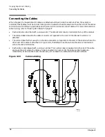
Page 230: ...Appendix G Connecting Multiple SPU Cabinets Connecting Cables 206 ...

Page 231: ...Exploration Tool or JET collects system information for each Superdome on a network and places it in files for use by other scan tools JET gathers configuration data by executing a series of queries targeted at the Maintenence Processor MP and the CLU portion of the UGUY board ...

Page 232: ...version information then exit d debug level Specifies JET debug level This parameter overrides any other specification of debug level h lower case h Prints short help page f complex name node number Causes a forced disconnect from the specified node in the specified complex i Enter interactive mode o Outputs the old format complex cfg configuration file The default is to output the new format cplx...

Page 233: ...owing options 1 Run JET 2 Display current configuration data 3 Update configuration X Exit Enter selection Select one of the options from the menu JET Run Menu By entering a 1 at the main JET menu it is placed in the run mode Figure H 2 shows the run menu options You may either interrogate all Superdome complexes of an individual complex Figure H 2 JET Run Display JET Interactive RUN MENU Select f...

Page 234: ...n menu enter 2 from the JET main menu as shown in Figure H 5 Figure H 5 Interactive Mode Display jet i JET Interactive MAIN MENU Select from the following options 1 Run JET 2 Display current configuration data 3 Update configuration X Exit Enter selection Figure H 6 Display Current Configuration Menu JET Interactive COMPLEX SELECTION MENU Select from the following options 1 feynman s X Return to p...

Page 235: ...ECTION MENU Select from the following options 0 Node number 0 1 Node number 1 2 Node number 2 3 Node number 3 4 Node number 4 5 Node number 5 6 Node number 6 7 Node number 7 8 Node number 8 9 Node number 9 10 Node number 10 11 Node number 11 12 Node number 12 13 Node number 13 14 Node number 14 15 Node number 15 X Return to previous menu Enter selection 0 Entering a node number yields a display th...

Page 236: ...t 0 CPU 5 NOT PRESENT UP_TO_DATE Board Slot 0 CPU 6 NOT PRESENT UP_TO_DATE Board Slot 0 CPU 7 NOT PRESENT UP_TO_DATE Board Slot 1 CPU 0 PRESENT UP_TO_DATE CPUMOD Board Slot 1 CPU 1 NOT PRESENT UP_TO_DATE Board Slot 1 CPU 2 NOT PRESENT UP_TO_DATE Board Slot 1 CPU 3 PRESENT UP_TO_DATE CPUMOD Board Slot 1 CPU 4 NOT PRESENT UP_TO_DATE Board Slot 1 CPU 5 NOT PRESENT UP_TO_DATE Board Slot 1 CPU 6 NOT PR...

Page 237: ...n in Figure H 10 Figure H 10 Interactive Mode Display jet i JET Interactive MAIN MENU Select from the following options 1 Run JET 2 Display current configuration data 3 Update configuration X Exit Enter selection When selecting the Update Configuration Option the menu shown in Figure H 11 is displayed which shows a list of available complexes Select the desired complex Figure H 11 Update Configura...

Page 238: ...rocessor Board JET Interactive BOARD FAMILY SELECTION MENU Select from the following options 2 BACKPLANE 3 PROCESSOR 5 IO X Return to previous menu Enter selection 3 Example H 3 Selecting a PDH Riser Board JET Interactive BOARD TYPE SELECTION MENU Select from the following options 1 CELL 2 PDH Card 3 Slot 0 CPU 4 Slot 1 CPU 5 Slot 2 CPU 6 Slot 3 CPU X Return to previous menu Enter selection 1 Exam...

Page 239: ...ION for path number 0 JET Interactive DEVICE SELECTION for path number 1 Select the correct device for jab Reference designator U33 1 jab 0x082b2291 2 jab 0x182b2291 3 jab 0x282b2291 Enter selection 3 Select the correct device for jab Reference designator U34 1 jab 0x082b2291 2 jab 0x182b2291 3 jab 0x282b2291 Enter selection 3 Select the correct device for jab Reference designator U43 1 jab 0x082b...

Page 240: ...r U3 1 jab 0x082b2291 2 jab 0x182b2291 3 jab 0x282b2291 Enter selection 3 Select the correct device for jab Reference designator U2 1 jab 0x082b2291 2 jab 0x182b2291 3 jab 0x282b2291 Enter selection 3 JET Interactive Update menu Select from the following options 1 Load new node configuration file 2 Add a Board to an existing node 3 Remove a Board from an existing node 4 Load flex mate file 5 Add a...

Page 241: ... H 13 JET Help Menu jet h usage jet d debug level f complex node h i v Where d debug level set debug level valid values are 0 4 f complex name node number force a disconnect h print this help page i interactive mode o Use old complex cfg file format r Perform Jtag resets on all paths prior to scanning s complex name interrogate only the specified complex v print JET version information ...

Page 242: ...eral parameters that define JET operation If the file is not found then JET uses its default values Each of the parameters described for this file may or may not be present If they are not present default parameters are used This file must be located in the directory from which JET is executed and must have the name jet cfg The following list describes parameters supported in the JET configuration...

Page 243: ...eter in the jet cfg file This overrides all other locations File Format There are two types of entries in the cplx ini The type of entry is present for a complex depends on whether the complex has multiple host entities or only a single host entity Multi host entries are specified with the key MH while single host entities are specified with the key SH Multi host entities have an additional parame...

Page 244: ...config directory Format Comments Comments in the board_name map file are specified by placing a character at the beginning of the line containing the comment End of line comments are not currently supported Version The first non comment field in the board_name map file must start with the keyword FILE_VERSION followed by the version number entered as a double FILE_VERSION version number Board Entr...

Page 245: ...mber and a presence mask available boolean If the mask available flag is TRUE then the next field is the bit in the mask representing this node if the flag is FALSE then this field is omitted The mask available field s are followed by the is host flag which indicates whether this entity is a host or not If the host flag is FALSE then the entity to which commands destine for node are to be sent is ...

Page 246: ...d has scan paths the number of paths on the board must be defined using the keyword num_scan_paths followed by an unsigned integer representing the number of scan paths on the board as follows num_scan_paths scan paths Masks By default a board is assumed to not have a presence mask If a presence mask does exist for this board then an entry defining the mask is required A mask entry begins with the...

Page 247: ...umber A path entry ends with the keyword End_Path Between these tags are board entries for each board composing the path Board Entries A board entry in a path begins with the keyword board followed by the family type and reference number of the board and the path on the board that is to be used These entries must be in order of how they appear on the path through the node as follows board board fa...

Page 248: ...esignator string Required flag TRUE FALSE Removal order integer NOTE The removal order determines which non required devices are missing if less than the maximum number of devices are encountered The lower the removal order the more likely the device is missing Link Connection Entries Each link connection to this board needs to have an entry in this file Link entries contain primary and secondary ...

Page 249: ... being processed End of File This file must end with the keyword End_Of_File Example H 14 Board Architecture File FILE_VERSION 4 0 Board_Path path number Board_Path1 Device ref num device name ref des required removal order Device6elroyU5007TRUE0 Device8dnaU5000FALSE1 End_Board_Path Link_Type link type Link_Type1 Secondary Connection ID lookup loopback type brd ref des cable ref des Connection10FA...

Page 250: ...er at the beginning of the line containing the comment End of line comments are not currently supported Version Infromation The first none comment field in the cplx ini file must start with the keyword FILE_VERSION followed by the files version entered as a double Example H 15 Device Architecture File Version FILE_VERSION version number Device Entries Each valid JTAG ID for this device must have a...

Page 251: ...tain entries for multiple complexes JET places this file in the default scan directory opt scansw data System entities represent MPs and nodes The data contained in this file provides information on what entities can be tested and the basics of how to communicate with each of the entities specified This file is normally created by JET Below is a description of each entry in the file Comments Comme...

Page 252: ... an entity is not a host then a reference to the target host entity must be supplied This reference specifies which host entity commands targeted to this entity must be directed This targeting entry begins with the keyword Target_Entity followed by the entity type GSP NODE and its reference number Target_Entity target entity type target entity ref number Firmware information entries Firmware Infor...

Page 253: ...tity type entity reference number Entity GSP0 host name protocol address port Hostname zurg s UDP 15 99 83 130 5151 queue depth queue size SDP version Firmware 165536 1 0 End_Entity entity type entity reference number Entity NODE 0 entity type entity reference number Target_Entity GSP 0 queue depthqueue size SDP version Firmware 16553 6 1 0 End_Entity End_Complex End_Of_File ...

Page 254: ...non static connections within the system needed to determine how the current system is connected There is only one flex link file for a complex and it must be named flex mte JET places this file in the default scan directory opt scansw data cplx_ hostname The flex mate file specifies all flex and cable connections for a complex This file only contains information on all possible links that could e...

Page 255: ...a in the file If an error is detected at the scan path level the path entry in the file will contain an error message that prevents JUST from loading the file but no other path data is affected In any of these cases a jet err file is created and an entry for the node is added to it If an error occurs at the node level the nodes entry is not placed in the complex cfg file If an error is detected du...

Page 256: ...Appendix H JUST Exploration Tool Error Conditions 232 ...

Page 257: ...pendix I 233 I Unpacking the SMS Connecting Cables and Setting SCSI Addresses This section contains a description of how to unpack rack cable and set SCSI addresses for the Support Management Station SMS ...

Page 258: ... the Support Management Station Unpack the Support Management Station SMS and related peripherals and equipment such as a DVD drive a DDS tape drive a peripheral housing The SMS and its peripherals can be placed on a table outside the I O expansion cabinet or in a rack See Installing the Support Management Station SMS on page 55 ...

Page 259: ...port Management Station and Peripherals If you put the Support Management Station SMS and its peripherals in a rack allow two EIA units for the A Class server the DVD player and the DDS tape drive To unpack and rack the SMS follow the A Class instructions that came with the server or refer to the following URL http class hp com hpus systems aclass ...

Page 260: ...at the last device is terminated Refer to the documentation accompanying each device to learn where to place terminators To connect the SMS peripherals and set SCSI addresses Step 1 Connect the cables between the SMS DDS tape drive and DVD Figure I 1Connecting DDS Tape and DVD CD ROM Drives to SMS Step 2 Connect the power cables one for each peripheral and one for the SMS Step 3 Set the SCSI ID of...

Reviews: