


Chapter 4
Verifying and Booting Superdome
Attaching Rear Kick Plates
98
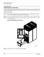
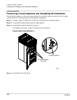
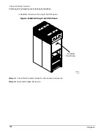
Attaching Rear Kick Plates
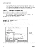
Kick plates serve the practical purpose of protecting cables from accidentally being disconnected or damaged,
as well as add an attractive cosmetic touch to the SPU cabinet. There are three metal pieces to attach to the
bottom rear of the cabinet.
To install the kick plates:
Step 1. Hold the left kick plate(A5201-0671) in position and attach a clip nut (0590-2318) on the cabinet
column next to the hole in the flange at the top of the kick plate.
Step 2. Using a screw (0515-0671) and a T25 Torx driver, attach the flange on the kick plate to the nut clip.
Step 3. Using a Torx 10 driver and a screw (0515-4271), attach the bottom of the kick plate to the center
hole in the leveling foot.
Figure 4-7Attaching Rear Kick Plates
Step 4. Perform steps 1-3 on the right kick plate (A5201-00281).
60IN078A
9/12/00
L3-L1
L1-L2
L2-L3
L2-L3
L1-L2
L3-L1
Summary of Contents for 9000 Superdome
Page 8: ...Contents 8 ...
Page 9: ...9 Preface ...
Page 21: ...21 IEC 60417 IEC 335 1 ISO 3864 IEC 617 2 International Symbols ...
Page 22: ...22 Figure 9 Superdome Declaration of Conformity Page 1 ...
Page 23: ...23 Figure 10 Superdome Declaration of Conformity Page 2 ...
Page 24: ...24 ...
Page 32: ...Chapter 1 Introduction Installation Warranty 8 ...
Page 130: ...Chapter 4 Verifying and Booting Superdome Enabling iCOD 106 ...
Page 172: ...Appendix A hp Server rx2600 Support Management Station Configuring the SMS 148 ...
Page 184: ...Appendix C Superdome LAN Interconnect Diagram 160 ...
Page 193: ...Appendix F 169 F A180 Support Management Station ...
Page 230: ...Appendix G Connecting Multiple SPU Cabinets Connecting Cables 206 ...
Page 256: ...Appendix H JUST Exploration Tool Error Conditions 232 ...


