


Appendix A
hp Server rx2600 Support Management Station
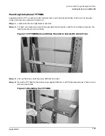
Installing the hp Server rx2600 SMS
141
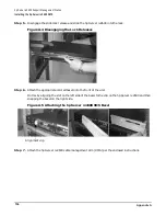
Connecting the SMS Cables
After the SMS components have been installed, connect them using the following procedure:
NOTE
Make sure all devices on the SCSI bus have a unique address and that the last device is
terminated. Refer to the documentation accompanying each device to learn where to place
terminators.
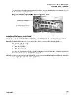
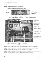
Step 1. Plug the hp Server rx2600, the Tape Array 5300, and the TFT5600 power cords from each unit to
the rack power strip and refer to Figure A-16 for the remaining connections.
Summary of Contents for 9000 Superdome
Page 8: ...Contents 8 ...
Page 9: ...9 Preface ...
Page 21: ...21 IEC 60417 IEC 335 1 ISO 3864 IEC 617 2 International Symbols ...
Page 22: ...22 Figure 9 Superdome Declaration of Conformity Page 1 ...
Page 23: ...23 Figure 10 Superdome Declaration of Conformity Page 2 ...
Page 24: ...24 ...
Page 32: ...Chapter 1 Introduction Installation Warranty 8 ...
Page 130: ...Chapter 4 Verifying and Booting Superdome Enabling iCOD 106 ...
Page 172: ...Appendix A hp Server rx2600 Support Management Station Configuring the SMS 148 ...
Page 184: ...Appendix C Superdome LAN Interconnect Diagram 160 ...
Page 193: ...Appendix F 169 F A180 Support Management Station ...
Page 230: ...Appendix G Connecting Multiple SPU Cabinets Connecting Cables 206 ...
Page 256: ...Appendix H JUST Exploration Tool Error Conditions 232 ...


