background image

Summary of Contents for 9120A

Page 1: ...W HEWTETT PACIIARD GATCUTATOR PRINTER Model 9120A H w ss w gs ...

Page 2: ...s for ninety 90 days from date of delivery We will repair or replace components which prove to be defective during the warranty period No other warranty is expressed or implied We are not liable for consequen tial damages For any assistance contact your nearest Hewlett Packard Sales and Service Office Addresses are provided on the last pages of this manual ...

Page 3: ...OPERATTilG IilSTRUCTIONS HEWLETT PACKARD 912OA sHowN wlTH gtoo ...

Page 4: ...RAL INFORMATION General Description Power Requirements Radio Frequency lnterference Grounding Requirements Accessories Equipment Supplied Cover Removal INSTALLATION PAPER LOADING INITIAL INSPECTION KEYBOARD 3 3 3 3 3 4 4 5 I 9v ...

Page 5: ...the line is under the voltage to be used GENERAL INFORMATION GENERAL DESCRIPTION POWER REQUIREMENTS RAD O FREQUET CY INTERFERENCE GROUNDING REQUIREMENTS 3 CAUTION DO NOT APPLY OPERATING POWER TO THE 9120A PRINTER UNLESS THE LINE VOLTAGE SWITCH ON THE REAR PANEL IS IN THE PROPER POSITION Radio Frequency lnterference RFl is generated by many electrical devices included in this group is the 9120A A p...

Page 6: ...ter Paper is available in 24 No 9270 0815 DESCRIPTION Operating Manual Power Cord 3 roll package of Printer Paper Dust Cover roll quantities HP Part should 2 v lf the top cover is removed the following caution be observed CAUTION IF THE PRINT FINGER ASSEMBLY IS MANUALLY ENGAGED ALWAYS TURN THE DRIVE BELT IN CLOCK WISE DIRECTION TURNING THE BELT IN THE COUNTERCLOCKWISE DIRECTION WITH THE PRINT FIN ...

Page 7: ...ing container and stand it on its rear edge Remove the four thumbscrews from the bottom of the printer CAUTION THE THUMBSCREWS WILL DAMAGE THE CALCULATOR S TOP IF THEY ARE NOT REMOVED RETAIN THE THUMBSCREWS THEY MUST BE REINSTALLED FOR SHIPMENT DrRtcTr0t 0t rot Ir0tt ctRcutAr H0r t Turn the plastic wings from their stored position to the fully extended position Notice the two circular holes that h...

Page 8: ...r skip at this point to Step 5 STEP 4 Turn the calculator off Connect the signal connector to the rear of the calculator lt is keyed to assist in installa tion c0intcT PRIÎ lITR POWER PtUG PNIilIER POWIR PTUG fl Ent stcf At c0iltitct0R lf the rear of the calculator has a receptacle which will accept the printer s power plug connect the two lf the rear of the calculator does not have the receptacle...

Page 9: ...calculator Turn the calculator off lnstall the printer signal connector in the rear of the plotter Connect the printer s power plug into the rear of the plotter lf the connectors will not mate use the supplied power cable adapter to make the connec tion 9 t00 9t20r PRrITtn srGft t c0ilrtcr0n A ...

Page 10: ... paper holders STEP 2 lnsert the paper over the roller and under the paper re lease Push the paper in as far as possible While still pushing on the paper depress paper load key When ap proximately two inches of paper has been taken up stop pushing the paper Hold the paper load key depressed until approximately one inch of paper shows above the paper release Y3 w2 r ...

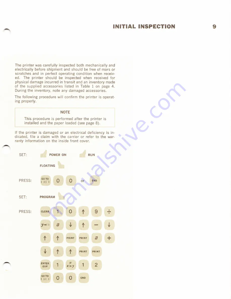
Page 11: ...accessories listed in Table I on page 4 During the inventory note any damaged accessories The following procedure will confirm the printer is operat ing properly lf the printer is damaged or an electrical deficiency is in dicated file a claim with the carrier or refer to the war ranty information on the inside front cover a SET PRESS SET PRESS 1f rrr on J un 30rA 3esffi cgas ttr Itt ltc FLoAnNc h ...

Page 12: ...1 INITIAL TNSPECTION V NOTE The expressions DEPRESS or RELEASE refer to printer keys DEPRESS SET PRESS DEPRESS PRESS n gf un t uru or G ...

Page 13: ...INITIAL INSPECTION t1 The program will continue until STOP is pressed PRESS sroP PRESS 111111 1111 JE 1 1 PRESS î PRESS 222222 2222 l 1 1 PRESS î PRESS 333333 3333 5 1 1 RELEASE t and z ...

Page 14: ...t2 TT ITIAL INSPECTTON PRESS RELEASE DEPRESS PRESS PRESS RELEASE DEPRESS PRESS PRESS DEPRESS DEPRESS PRESS m G TT ffi e r1 W 0 C TD m PRESS ...

Page 15: ...INITIAL I ISPEGTTON 13 PRESS DEPRESS lll r t r î ...

Page 16: ... Successive print instructions programmed or manual will result in the first instruction caus ing the registers selected to be printed and the remaining print instructions causing the printer to space lf a duplication of register printing is desired insert any calculator instruction man ual or programmed between the print instruc tions Will cause the printing of the contents of the calculator s me...

Page 17: ...space The Paper Release will remove tension on the printer paper so the paper may be removed from the print mech anism To release the tension pull the Paper Release to ward the front of the printer until a click is heard KEYBOARD PAPER RELEASE 15 ...

Page 18: ...nstruments with other serial prefixes check for errata below and make changes sholn in tables lnstrument Serial Prefixes l4ake Manual Changes G 948 and above ERRATA 0n Page 4 Table 1 For instruments equipped rvith German rrSchukorr Power Cable change the hp Part No of poler Cable to 8120 1349 Page I MODEL 9120 A Dec I l 1969 ...

Page 19: ... above ALABAMA P 0 Box 4207 2003 Byrd Spring Road S VY tlunttvllle 35802 fel 205 881 4591 îWX 810 726 2204 ARIZONA 3009 Norlh Scollsdale Road Scotirdrle 85251 fel 602 945 7601 lwx 910 950 1282 5737 East Sroadway fucaor 85716 lel 602 298 2313 twx 910 9s2 1152 CALIFORNIA 1430 East orangethorpe Ave frllarton 92631 fel 7r4 870 r000 3939 l ankershlm Eoulevard Iorli Hollrrood 91604 fel 1213 877 1282 flf...

Page 20: ...kard Australia Pty Ltd 2nd Floor Suite 13 Casablanca Buildings 196 Adelaide lèrrace Perth V 4 6000 CEYLON United Electricals Ltd P 0 8ox 681 Yahala Euildins Staples Street Colonùo 2 Tel 5496 Cable H0TP0lt l Colombo CYPRUS Kypronics 19 190 Hommer Avenue P 0 8ox 752 ilicosi Tel 6282 7562E Cable HE l NAMI ETT IOPIA Al ican Salespower Agency Private Ltd Co P O gox 718 58 59 Cunningham St Addis Aùùr le...

Page 21: ...v v V PRINTED IN U S A PART NO 09r20 90000 NOV r r9ó9 ...

Reviews: