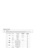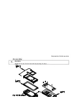
Calibration Table
CAUTION
Dangerous voltages are present during the calibration procedure. Calibration should only be
performed by qualified service technicians using a non-conductive tool.
Step
Function
Range
Input Signal
Adjustment
(limits)
Tolerance
(counts)
1
mV
400 mV
Short
—
±
1
2
380.0 mV
RV1 (
±
1)
±
12
3
-380.0 mV
—
±
12
4
V
4 V
3.800 V
RV2 (
±
1)
±
12
5
40 V
38.00 V
—
±
12
6
400 V
380.0 V
—
±
12
7
1000 V
1000 V
—
±
4
8
V
400 V
380.0 V @ 100 Hz
RV3 (
±
1)
±
40
9
380.0 V @ 1 kHz
—
±
61
10
mV
400 mV
380.0 mV @ 100 Hz
—
±
40
11
380.0 mV @ 1 kHz
—
±
61
12
V
4 V
3 .800 V @ 100 Hz
—
±
40
13
3.800 V @ 1 kHz
—
±
61
14
40 V
38.00 V @ 100 Hz
—
±
40
15
38.00 V @ 1 kHz
—
±
61
16
1000 V
1000 V @ 100 Hz
—
±
12
17
µ
A
400
µ
A
380.0
µ
A
—
±
21
18
4000
µ
A
3800
µ
A
—
±
40
19
mA
40 mA
38.00 mA
—
±
40
20
400 mA
380.0 mA
—
±
47
6-2
Summary of Contents for 971A
Page 2: ...HP 971A Multimeter User s Guide Part Number 00971 90002 March 1995 ...
Page 3: ......
Page 22: ...Adjustments ...


