background image

2-40 HP Portable Chillers

Chapter 7: Appendix

60 of 78

Water Pressure Drop Tables

Note: 

A recirculation pump is required for flows greater than the
maximum or less than the minimum indicated.

Note: 

Process flow less than or greater than the flow rates shown below
requires a recirculation pump.

Pressure drops in 

P, psig and 

kPa

2 HP

3.5 HP

5 HP

7.5 HP

Flow

 P

Flow

 P

Flow

 P

Flow

 P

gpm

lpm

psig

kPa

gpm

lpm

psig

kPa

gpm

lpm

psig

kPa

gpm

lpm

psig

kPa

4.06

15.4

3.5

24.1

8.03

30.4

4.0

27.6

10.0

37.9

1.5

10.5

12.0

45.4

2.3

16.1

6.01

22.8

7.0

48.3

10.00

37.9

6.5

44.8

12.0

45.4

2.2

14.8

16.0

60.6

2.9

20.1

8.02

30.4

11.5

79.3

12.00

45.4

10.0

69.

18.0

68.1

4.7

32.1

20.0

75.7

5.0

34.5

10.00

37.9

18.0

124.1

14.00

53.0

13.0

89.6

24.0

90.8

7.3

50.2

24.0

90.8

6.9

47.4

16.00

60.6

18.0

124.1

28.0

106.0

9.6

65.9

33.0

124.9

12.7

87.8

10 HP

15 HP

20 HP

25 HP

Flow

 P

Flow

 P

Flow

 P

Flow

 P

gpm

lpm

psig

kPa

gpm

lpm

psig

kPa

gpm

lpm

psig

kPa

gpm

lpm

psig

kPa

22.0

83.3

4.7

32.6

30.0

113.6

4.5

31.3

40.0

151.4

4.0

27.6

55.0

208.2

5.5

37.9

30.0

113.6

8.28

57.1

40.0

151.4

7.5

51.7

45.0

170.3

4.0

27.6

58.0

219.5

5.8

40.0

38.0

143.8

12.91

89.0

50.0

189.3

12.4

85.2

50.0

189.3

5.0

34.5

61.0

230.9

6.0

41.4

46.0

174.1

16.77

115.6

60.0

227.1

17.8

122.8

52.0

196.8

6.0

41.4

70.0

264.9

8.5

58.6

50.0

189.3

20.00

137.9

70.0

264.9

24.2

166.6

55.0

208.2

6.5

44.8

30 HP

35 HP

40 HP

Flow

 P

Flow

 P

Flow

 P

Flow

 P

gpm

lpm

psig

kPa

gpm

lpm

psig

kPa

gpm

lpm

psig

kPa

gpm

lpm

psig

kPa

72.0

272.5

6.0

41.1

38.7

146.5

1.5

10.4

92.6

350.5

7.9

54.5

44.7

169.2

2.0

13.8

75.0

283.9

6.5

44.8

51.2

193.8

2.6

17.9

107.1

405.4

10.4

71.7

58.5

221.4

3.4

23.4

80.0

302.8

8.0

55.2

62.3

235.8

3.8

26.2

70.9

268.3

4.9

33.8

85.0

321.7

9.5

65.5

71.8

271.7

4.9

33.8

81.6

308.8

6.3

43.5

82.9

313.7

6.5

44.8

105.7

400.0

10.3

71.0

Note: 

These pressure drop values are valid for single- and no-pump
portable chillers.

Calculating Chiller Nominal Flow and Pressure to Process


Flow rate:

 Obtain the flow reading from the appropriate pump curve.


Pressure:

 Obtain a corresponding pressure reading from the pump curve you selected,

then 

subtract

 the one-pump pressure drop listed in the above table using the

appropriate chiller hp and flow rate.


For two

-

pump (Process/Recirc) chillers, do not subtract pressure drop from table above

for process pump.

Summary of Contents for A0554832

Page 1: ...____________ _________________________ _________________________ _________________________ _________________________ _________________________ We are committed to a continuing program of product improvement Specifications appearance and dimensions described in this manual are subject to change without notice DCN No ____________ Copyright 2004 All rights reserved ...

Page 2: ...tached to our original invoice If the shipment was prepaid write us for a receipted transportation bill Advise customer service regarding your wish for assistance and to obtain an RMA return material authorization number If the Shipment is Not Complete Check the packing list as back ordered items are noted on the packing list In addition to the equipment itself you should have Bill of lading Packi...

Page 3: ...trol 12 Crankcase Heater 12 High Pressure Cutout 12 Low Pressure Cutout 13 Oil Pressure Safety Switch 13 Fan Cycling Switch 13 Pressure Switch 13 Flow Switch 13 Remote Start Stop Interlock 13 2 5 Optional Features 14 CHAPTER 3 INSTALLATION 17 3 1 Uncrating 17 3 2 Electrical Connections 17 3 3 Process Water Connections 18 3 4 Bypass Valve Considerations 18 3 5 Galvanic Corrosion Considerations 18 3...

Page 4: ... 44 Parts Department 44 Service Department 44 Sales Department 44 Contract Department 44 7 3 Drawings and Specifications 45 2 hp and 3 1 2 hp Air Cooled Portable Chillers 45 5 hp and 7 5 hp Air Cooled Portable Chillers 46 10 hp and 15 hp Air Cooled Portable Chillers 47 20 hp 25 hp and 30 hp Air Cooled Portable Chillers 48 2 hp and 3 5 hp Water Cooled Portable Chillers 49 5 hp and 7 5 hp Water Cool...

Page 5: ...chematic 5 hp through 40 hp No Pump Models 68 Typical Piping Schematic 5 hp through 40 hp One Pump Models 69 7 8 Electrical Schematics 70 Typical Electrical Subpanel 70 Typical Electrical Schematic 2 hp and 3 1 2 hp Models 71 Typical Power Wiring Schematic 5 hp through 40 hp Models 72 Typical Wiring Schematic 5 hp through 15 hp Models with Pump 73 Typical Wiring Schematic 5 hp through 15 hp Models...

Page 6: ...trols in addition to information for operating the equipment safely and efficiently The Maintenance chapter is intended to serve as a source of detailed assembly and disassembly instructions for those areas of the equipment requiring service Preventive maintenance sections are included to ensure that your equipment provides excellent long service The Troubleshooting chapter serves as a guide for i...

Page 7: ...develop refrigerant pressures in excess of 500 psi 3 447 5 kPa 34 47 bars DO NOT CUT INTO THE REFRIGERATION SYSTEM This must be performed by a qualified service technician only Do not restore power until you remove all tools test equipment etc and the equipment and related components are fully reassembled Only PROPERLY TRAINED personnel familiar with the information in this manual should work on t...

Page 8: ...ons for air and water cooled portable chillers Model numbers are listed on the serial tag Make sure you know the model and serial number of your equipment before contacting the manufacturer for parts or service Our portable chiller models are designated by approximate compressor horsepower 2 3 1 2 5 7 1 2 10 etc and the cooling method used A for air cooled W for water cooled and R for remote air c...

Page 9: ...ns It is not intended to provide continuous full bypass flow This minimal flow allows the temperature sensor to signal the controller to shut down the compressor because of the drop in process water temperature Typically the flow switch shuts down the chiller in this low flow condition The 2 hp and 3 1 2 hp models have a 1 4 poly tubing constant bypass to provide additional process water bypass to...

Page 10: ...nk 10 hp and 15 hp models use a 40 gallon polyethylene tank 20 hp to 30 hp models use an 80 gallon polyethylene tank and 35 hp and 40 hp models use an 80 gallon stainless steel tank Piping Non ferrous piping for 2 hp through 30 hp models 35 hp and 40 hp models have ferrous piping Pump Non overloading ODP motors horizontally mounted stamped stainless steel or cast bronze construction Other Mechanic...

Page 11: ...ervice valves Hot gas bypass and liquid line shut off ball valves on 5 hp to 40 hp models Filter dryer Sight glass Balanced port thermal expansion valve Controller Features Off the shelf microprocessor based PID auto tuning controller with To Process and Set Point LED readout Microprocessor temperature switch with LCD display for process water freeze protection compressor cutout and high process w...

Page 12: ...ing of the components by the process water glycol The thermostat stage two cutout temperature is factory set at 100ºF 38ºC See Section 4 6 on page 36 for information about changing the thermostat settings Caution Protect the system from freezing with glycol 20ºF below the leaving water temperature set point Condensation may form inside the pump tank and dilute the mixture therefore the freezing po...

Page 13: ... have one fan The fan cycling switch turns on the fan when the discharge pressure in the condenser reaches 300 psi and turns it off when the pressure drops below 190 psi 10 hp to 30 hp models have two fans One fan runs continuously every time the compressor operates The second fan turns on when the discharge pressure in the condenser reaches 275 psi and turns off when the pressure drops below 200 ...

Page 14: ... 000 peak candlepower 80 flash min visual alarm strobe and silence button with provisions for customer wiring indication interlock The alarm signals anytime that a fault is recognized during the operation of the chiller Compressor Hour Meter Includes a DIN mount hour meter that keeps track of the total time that the compressor runs Communications Options RS 232C and RS 485 communications standards...

Page 15: ...for other voltages UL Labeled Electrical Subpanel Provides for the subpanel to be listed with Underwriters Laboratory with UL related benefits and features Optional Pumps Pump options are available for greater pressure and flow rates A recirculation pump is required whenever process water flow is less than 2 2 gpm per ton or greater than 4 8 gpm per tone See Figure 1 on page 16 for optional pump a...

Page 16: ...f 78 Figure 1 Optional Pump Amperages Voltage Construction HP Full Load Amps Bronze Turbine 75 5 4 1 6 4 1 5 7 5 2 9 6 208 230 1 60 SS 3 12 7 Bronze Turbine 75 1 5 1 1 8 1 5 2 3 2 3 1 3 4 2 5 6 2 7 5 9 8 10 13 2 SS 15 19 0 2 2 7 3 4 5 5 6 6 460 3 60 Dual SS 7 5 9 0 ...

Page 17: ...s and can then be moved into position 5 Temporary hardware has been installed to prevent side panels from shifting in transit Remove hardware 6 Retain the crating material for reshipping the chiller in case hidden shipping damage is found Caution Never remove the unit from the front electrical control end or the rear pipe connection end Damage may result 3 2 Electrical Connections Supply electrici...

Page 18: ...llows a small amount of water to flow through the chiller This action protects the chiller from freeze up and allows the other cutout devices to shut down the chiller The bypass valve is not intended to provide continuous full bypass flow Caution Do not attempt to adjust or otherwise tamper with the bypass valve Your warranty will be voided 3 5 Galvanic Corrosion Considerations The materials used ...

Page 19: ...approved discharge receiver A water regulating valve is a standard feature in the condenser water return line Air Cooled Chiller Condensers Air cooled chillers use the surrounding air to cool the condenser Install the chiller in an area where there is free passage of air for condensing and provisions for removal of heated air from the area Do not locate air cooled chillers in locations where steam...

Page 20: ...cause this will allow copper chips to contaminate the system A certified refrigeration contractor need only to install the interconnecting refrigerant piping between the chiller and the outdoor air cooled condenser This piping must be properly sized type L or type K refrigerant grade tubing high temperature brazed Install a customer supplied 400 psi approved refrigerant relief valve in the dischar...

Page 21: ...Lines To determine field installed liquid and discharge line sizes first establish the equivalent length of pipe for each line valve and elbow Chiller capacity and leaving water temperature range is also required See Figure 2 on page 22 for lengths of refrigerant valves and fittings Liquid Line Sizing The liquid line should be sized as small as possible while maintaining acceptable pressure drop t...

Page 22: ... 5 8 5 8 7 8 7 8 7 8 1 1 8 1 1 8 1 1 8 1 1 8 225 5 8 5 8 7 8 7 8 1 1 8 1 1 8 1 1 8 1 1 8 1 3 8 250 5 8 5 8 7 8 7 8 1 1 8 1 1 8 1 1 8 1 1 8 1 3 8 275 5 8 5 8 7 8 7 8 1 1 8 1 1 8 1 1 8 1 1 8 1 3 8 300 5 8 5 8 7 8 7 8 1 1 8 1 1 8 1 1 8 1 3 8 1 3 8 Figure 4 Discharge Line Sizing 30 65 F Leaving Water Temperature Discharge Line Size O D Eqiv FT 5 hp 7 5 hp 10 hp 15 hp 20 hp 25 hp 30 hp 35 hp 40 hp 25 7...

Page 23: ...5 Refrigerant Charge Determination Chiller Condenser Charge Field Installed Piping Charge Horsepower Lbs of R 22 Pipe O D Inches Discharge Line c R 22 Lbs Liquid Line c R 22 Lbs 5 5 9 1 2 7 2 7 5 6 1 5 8 11 5 10 10 8 7 8 1 6 24 0 15 12 6 1 1 8 2 7 40 9 20 21 2 1 3 8 4 0 62 2 25 24 2 1 5 8 5 7 88 1 30 40 2 2 1 8 10 0 153 0 35 41 2 2 5 8 15 0 236 0 40 50 2 c Based on 100 feet of pipe 100 ºF Liquid 1...

Page 24: ...Compressors Scroll compressors are directionally dependent and compress in one rotational direction Reversing rotation direction results in an elevated sound level and a substantially reduced current draw Water Pumps Correct pump rotation is indicated by a positive pressure of 20 to 40 psi on the pump pressure gauge Pump rotation should be clockwise when viewed from the motor end For chillers with...

Page 25: ...gallons 208 2 liters A0542990 Propylene glycol 5 gallons 18 9 liters A0542991 Propylene glycol 55 gallons 208 2 liters Caution Do not connect make up water directly to the chilled water reservoir unless you have an approved automatic water make up system installed The reservoir is not designed to withstand water pressure The fill opening and vent line must be vented to the atmosphere for proper op...

Page 26: ...l Curves Pe rce nt Glyc ol Cu rves for Free ze Protec tion 60 0 50 0 40 0 30 0 20 0 10 0 0 0 10 0 20 0 30 0 40 0 0 0 10 0 20 0 30 0 40 0 50 0 60 0 Gl ycol by Vol um e Eth ylene G lycol Prop ylene Glycol Example 45 F set point minus 20 F 25 F From Figure 28 25 F equates to 10 by volume of glycol required ...

Page 27: ...gulating valve to limit make up water pressure to less than 5 psi The reservoir must remain vented to the atmosphere If the automatic make up system is connected to a city water system make provisions to prevent backflow contamination Install an approved backflow preventer in accordance with local codes Caution Adding straight city water into a glycol water mixture dilutes the solution and eventua...

Page 28: ...ank and chilled water circuit piping are filled to the full mark with a water glycol mixture The water glycol mixture should provide for freeze protection to at least 20 F 11ºC below the leaving water temperature you want The air cooled condenser should have an adequate supply of 60º to 95ºF 16º to 35ºC air for proper operation The tower or city water condenser cooling in and out connections shoul...

Page 29: ...mocouple It also lists parameter symbols during setup and error messages if an error occurs SV 8 8 8 8 Set Value LED During normal operation the green SV LED on the controller displays the process set point you want the chiller to maintain It also displays parameter and pre set function values during set up OUT1 Out 1 LED The orange OUT1 LED lights when the control output energizes the hot gas byp...

Page 30: ...ach press of the Up Arrow key increments or advances the values or settings on the SV display Sterlco 2000 Controller Indicator Name Description T 8 8 8 8 Process Value LED During normal operation the large red T LED on the controller displays the actual process temperature at the To Process thermocouple It also lists parameter symbols during setup and error messages if an error occurs SP 8 8 8 8 ...

Page 31: ...HP Portable Chillers Chapter 4 Operation 31 of 78 Figure 7 Typical Portable Chiller Microprocessor Controllers PV SV OUT1 OUT2 MANU STOP RMT AT SUB1 AT E5CK OMRON SP T MADE IN U S A 2 0 0 0 HT CL AL REM F C ...

Page 32: ... down the process water glycol pump s and the chiller shuts off This action prevents possible system failure from overheating of the process water glycol Pump On Light The Pump On light installed on chillers with a pump lights whenever the pump s operates High Discharge Temperature Light The High Discharge Temperature light comes on if the compressor discharge line temperature switch opens This sw...

Page 33: ...partment Low Oil Pressure Light The Low Oil Pressure light is installed on chillers with a semi hermetic compressor that have an oil pump A differential pressure switch monitors the difference between crankcase pressure and oil pump pressure If the pressure drops to an unsafe level for more than two minutes the switch will open the control wiring circuit shutting off the compressor turning the lig...

Page 34: ...MPERATURE HIGH TEMPERATURE HIGH DISCHARGE TEMPERATURE HIGH REFRIGERANT PRESSURE LOW REFRIGERANT PRESSURE LOW OIL PRESSURE ON OFF CONTROL POWER A0554705 SILENCE ALARM COMPRESSOR ON HOT GAS BY PASS PUMP ON PUMP OVERLOAD LOW WATER FLOW PRESSURE LOW TEMPERATURE HIGH TEMPERATURE HIGH DISCHARGE TEMPERATURE HIGH REFRIGERANT PRESSURE LOW REFRIGERANT PRESSURE LOW OIL PRESSURE PV SV OUT1 OUT2 MANU STOP RMT ...

Page 35: ...lco 2000 Controller To change the process water temperature set point press the Index key then press the Up Arrow button to raise the set point or the Down button to lower the set point Press the Enter key for the controller to accept the new values Press the Index key to return to the Home position 4 4 Auto Tuning E5CK Controller Only The Auto Tune function lets you fine tune the control PID to p...

Page 36: ...hermostat The keypad is disabled when the switch is moved to the left in the Lock position The keypad functions normally when the switch is moved to the right in the Unlock position All chillers are shipped with the switch in the Lock position Thermostat Buttons Indicator Name Description Set Button The Set button is used to enter the programming mode for the thermostat Up Arrow button Each press ...

Page 37: ... differential The setting should be 12ºF 4 Press the Set key again to access Stage 1 cooling or heating mode The screen displays the current mode C1 for cooling or H1 for Heating Use the Up Arrow and Down Arrow keys to toggle between C1 or H1 The setting should be C1 Stage 2 High Temperature Protection 5 Press the Set key again to access the high temperature set point The screen displays the curre...

Page 38: ...ed portable chiller operating at peak efficiency and capacity Clean the filters whenever they appear dirty or at regularly scheduled intervals 1 Turn the chiller off 2 Slide the filter up off of the retaining pins holding it in place along its bottom 3 Tip the bottom of the filter away from the chiller 4 Slide it down and out 5 Wash down the filter with clean water preferably with a garden hose di...

Page 39: ...ctions on the container The refrigerant side is sealed and requires no routine maintenance Caution Do not use steam or water over 140ºF 60ºC to clean a condenser unless you are monitoring the refrigeration circuit for excessive pressure with gauges Only a trained technician should use this method 5 4 Maintaining the Evaporator Dirty evaporator heat exchange surfaces reduce system capacity and effi...

Page 40: ...aintenance requirements These inspections include but are not limited to Checking refrigerant suction and discharge pressures Checking safety and operating conditions Checking voltage and amperage of all motors Checking all electrical connections Checking quantity of refrigerant Checking compressor oil level Checking lubrication of motor and pump bearings Checking circulating pump operation Checki...

Page 41: ...lear and the moisture indicator should be green while compressor is running Bubbles or foaming is normal when the hot gas by pass solenoid is energized Call for service if bubbling is occurring and or moisture indicator is yellow Clean the air filters Check condenser fans for proper rotation Check for dirty condenser Refrigerant high pressure indicator on Reset and test Fan motor out on overload R...

Page 42: ...en have refrigerant added Pump running in reverse Verify rotation if running in reverse rotation reverse any two main power leads Re verify for correct pump rotation Pump pressure low refer to curves for normal pressure for various pumps Check for foreign matter Clean the system Pump pressure is too high Restricted water flow Check for partially closed valves etc Make sure that all lines are prope...

Page 43: ... including freezing or which has been repaired or altered without the manufacturer s express authorization If the serial number has been defaced or removed from the component the warranty on that component is void Defective parts become the property of the warrantor and are to be returned The manufacturer is not liable for any incidental consequential or special damages or expenses The manufacture...

Page 44: ...r parts needs and is dedicated to providing excellent customer service Service Department Call toll free 8am 5pm CST 800 657 4679 or call 414 354 0970 Emergencies after 5pm CST call 847 439 5655 We have a qualified service department ready to help Service contracts are available for most of our products Sales Department Call 414 354 0970 Monday Friday 8am 5pm CST Our products are sold by a world w...

Page 45: ... cap per 0 746 kW pump power d Based on 2 4 gpm per ton 9 1 lpm per 3 517 kW nominal 1 pump e An optional oversized process pump adds to the total rated or running chiller amperage To find the new total chiller amperage subtract the standard process pump amperage from the optional pump amperage see Figure 1 on page 16 and add it to the chiller rated or running amperage f Multiply 460 3 60 amperage...

Page 46: ...ctwork requires optional high pressure fan for 5 hp to 15 hp 3 73 kW to 11 20 kW models f An optional oversized process pump adds to the total rated or running chiller amperage To find the new total chiller amperage subtract the standard process pump amperage from the optional pump amperage see Figure 1 on page 16 and add it to the chiller rated or running amperage g Multiply 460 3 60 amperage by ...

Page 47: ... requires optional high pressure fan for 5 hp to 15 hp 3 73 kW to 11 20 kW models f An optional oversized process pump adds to the total rated or running chiller amperage To find the new total chiller amperage subtract the standard process pump amperage from the optional pump amperage see Figure 1 on page 16 and add it to the chiller rated or running amperage g Multiply 460 3 60 amperage by 2 0 fo...

Page 48: ...per 3 517 kW nominal 1 pump e An optional oversized process pump adds to the total rated or running chiller amperage To find the new total chiller amperage subtract the standard process pump amperage from the optional pump amperage see Figure 1 on page 16 and add it to the chiller rated or running amperage f Multiply 460 3 60 amperage by 2 0 for 208 230 3 60 amperages multiply by 0 8 for 575 3 60 ...

Page 49: ... 3 517 kW nominal 1 pump e Based on availability of 85ºF 29ºC tower water at 25 psi 172 4 kPa 1 7 bars minimum f Based on availability of 70ºF 21ºC city water at 25 psi 172 4 kPa 1 7 bars minimum g An optional oversized process pump adds to the total rated or running chiller amperage To find the new total chiller amperage subtract the standard process pump amperage from the optional pump amperage ...

Page 50: ...7 kW nominal 1 pump e Based on availability of 85ºF 29ºC tower water at 25 psi 172 4 kPa 1 7 bars minimum f Based on availability of 70ºF 21ºC city water at 25 psi 172 4 kPa 1 7 bars minimum g An optional oversized process pump adds to the total rated or running chiller amperage To find the new total chiller amperage subtract the standard process pump amperage from the optional pump amperage see F...

Page 51: ...W nominal 1 pump e Based on availability of 85ºF 29ºC tower water at 25 psi 172 4 kPa 1 7 bars minimum f Based on availability of 70ºF 21ºC city water at 25 psi 172 4 kPa 1 7 bars minimum g An optional oversized process pump adds to the total rated or running chiller amperage To find the new total chiller amperage subtract the standard process pump amperage from the optional pump amperage see Figu...

Page 52: ...nominal 1 pump e Based on availability of 85ºF 29ºC tower water at 25 psi 172 4 kPa 1 7 bars minimum f Based on availability of 70ºF 21ºC city water at 25 psi 172 4 kPa 1 7 bars minimum g An optional oversized process pump adds to the total rated or running chiller amperage To find the new total chiller amperage subtract the standard process pump amperage from the optional pump amperage see Figure...

Page 53: ...minal 1 pump e Based on availability of 85ºF 29ºC tower water at 25 psi 172 4 kPa 1 7 bars minimum f Based on availability of 70ºF 21ºC city water at 25 psi 172 4 kPa 1 7 bars minimum g An optional oversized process pump adds to the total rated or running chiller amperage To find the new total chiller amperage subtract the standard process pump amperage from the optional pump amperage see Figure 1...

Page 54: ...pm per ton 9 1 lpm per 3 517 kW nominal 1 pump e An optional oversized process pump adds to the total rated or running chiller amperage To find the new total chiller amperage subtract the standard process pump amperage from the optional pump amperage see Figure 1 on page 16 and add it to the chiller rated or running amperage f Multiply 460 3 60 amperage by 2 0 for 208 230 3 60 amperages multiply b...

Page 55: ...m per ton 9 1 lpm per 3 517 kW nominal 1 pump e An optional oversized process pump adds to the total rated or running chiller amperage To find the new total chiller amperage subtract the standard process pump amperage from the optional pump amperage see Figure 1 on page 16 and add it to the chiller rated or running amperage f Multiply 460 3 60 amperage by 2 0 for 208 230 3 60 amperages multiply by...

Page 56: ...lpm per 3 517 kW nominal 1 pump e An optional oversized process pump adds to the total rated or running chiller amperage To find the new total chiller amperage subtract the standard process pump amperage from the optional pump amperage see Figure 1 on page 16 and add it to the chiller rated or running amperage f Multiply 460 3 60 amperage by 2 0 for 208 230 3 60 amperages multiply by 0 8 for 575 3...

Page 57: ...8 43 0 40 5 120 0 15 8 11 8 6 4 20 30 1 1 2 hp 3 ø 5 9 2 23 000 840 125 0 45 5 50 0 108 0 15 8 15 8 10 0 25 30 1 1 2 hp 3 ø 5 9 2 21 900 860 125 0 45 5 50 0 108 0 15 8 15 8 16 0 30 30 1 1 2 hp 3 ø 9 4 3 34 800 1 280 180 0 45 5 50 0 i 21 8 21 8 24 0 35 30 1 1 2 hp 3 ø 9 4 3 32 900 1 300 180 0 45 5 50 0 i 21 8 21 8 24 0 40 30 1 1 2 hp 3 ø 12 9 4 46 400 1 690 235 0 45 5 50 0 i 21 8 21 8 29 0 c ø repr...

Page 58: ...2 40 HP Portable Chillers Chapter 7 Appendix 58 of 78 7 4 Pump Curves Flow and Pressure Considerations 60 Hertz Pump Curves DWG No A0554823 ...

Page 59: ...2 40 HP Portable Chillers Chapter 7 Appendix 59 of 78 50 Hertz Pump Curves DWG No S0554823 ...

Page 60: ... 1 40 0 151 4 7 5 51 7 45 0 170 3 4 0 27 6 58 0 219 5 5 8 40 0 38 0 143 8 12 91 89 0 50 0 189 3 12 4 85 2 50 0 189 3 5 0 34 5 61 0 230 9 6 0 41 4 46 0 174 1 16 77 115 6 60 0 227 1 17 8 122 8 52 0 196 8 6 0 41 4 70 0 264 9 8 5 58 6 50 0 189 3 20 00 137 9 70 0 264 9 24 2 166 6 55 0 208 2 6 5 44 8 30 HP 35 HP 40 HP Flow P Flow P Flow P Flow P gpm lpm psig kPa gpm lpm psig kPa gpm lpm psig kPa gpm lpm...

Page 61: ...0 41 2 1 0 746 31 7 218 5 2 2 W 5 hp 12 6 47 7 2 3 16 00 1 0 746 34 3 236 2 2 4 W 7 5 hp 17 0 64 5 3 1 21 4 1 0 746 32 0 220 3 2 2 W 10 hp 25 7 97 4 6 3 43 3 2 1 492 41 4 285 3 2 9 W 15 hp 38 1 144 1 7 0 48 1 2 1 492 35 5 244 4 2 4 W 20 hp 50 4 190 8 8 8 60 3 5 3 73 52 0 358 5 3 6 W 25 hp 61 7 233 7 9 0 62 1 5 3 73 49 0 337 9 3 4 W 30 hp 76 2 288 5 10 8 74 1 5 3 73 43 0 296 5 3 0 W 35 hp 82 0 310 ...

Page 62: ...table Chillers Chapter 7 Appendix 62 of 78 7 5 Remote Air Cooled Chiller Configurations Configuration A Liquid line riser should not exceed 15 feet from base of air cooled condenser Configuration B Configuration C ...

Page 63: ...ion for models 5 through 15 hp Allow 30 77 cm minimum clearance around the chiller footprint to facilitate free passage of cooling air and service accessibility Size the ductwork for maximum capacity Support ductwork from the building structure not off of the chiller Back draft damper to outside must be closed at all times when fan blower is not operating Chillers with dual fans blower must have a...

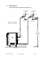
Page 64: ...2 40 HP Portable Chillers Chapter 7 Appendix 64 of 78 7 7 Piping Diagrams Central and Gravity Return Piping with Standpipe Diagram ...

Page 65: ...2 40 HP Portable Chillers Chapter 7 Appendix 65 of 78 Typical Piping Schematic 2 and 3 1 2 hp Models µ ...

Page 66: ...2 40 HP Portable Chillers Chapter 7 Appendix 66 of 78 Typical Piping Schematic 5 hp through 40 hp One Pump Models ...

Page 67: ...2 40 HP Portable Chillers Chapter 7 Appendix 67 of 78 Typical Piping Schematic 5 hp through 40 hp Two Pump Models µ ...

Page 68: ...2 40 HP Portable Chillers Chapter 7 Appendix 68 of 78 Typical Piping Schematic 5 hp through 40 hp No Pump Models ...

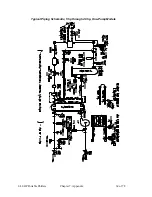
Page 69: ...2 40 HP Portable Chillers Chapter 7 Appendix 69 of 78 Typical Piping Schematic 5 hp through 40 hp One Pump Models ...

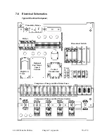
Page 70: ...f 78 7 8 Electrical Schematics Typical Electrical Subpanel Time delay Relays Relays Optional Fan Motor Speed Control Control Transformer Fuses High Low T stat Disconnect Switch Compressor Pump and Fan Motor Fuses Compressor Pump and Fan Motor Starters ...

Page 71: ...2 40 HP Portable Chillers Chapter 7 Appendix 71 of 78 Typical Electrical Schematic 2 hp and 3 1 2 hp Models ...

Page 72: ..._______ 4MTR 4T3 S C FUSE SIZE ________ CAPACITOR FLA ________ FUSE SIZE ________ 1L2 1L1 1L3 1L1 1L2 1L3 2L1 FUSE SIZE _____ WIRING BY OTHERS LOCATED OUTSIDE COMPONENT OF ENCLOSURE OPTIONAL FEATURE LOW AMBIENT AIR COOLED AIR COOLED STANDARD AND HIGH PRESSURE A0554815 1DISC 1L1 1L2 1L3 1DB GROUNDING BAR 3FU 3L1 3L2 3L3 1C 1T1 1T2 1T3 1MTR COMPRESSOR ________ HP 4FU 4L1 4L2 4L3 1M 1OL 2T1 2T2 2T3 2...

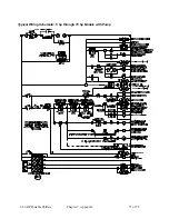
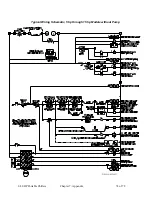
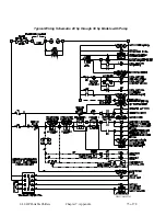
Page 73: ...2 40 HP Portable Chillers Chapter 7 Appendix 73 of 78 Typical Wiring Schematic 5 hp through 15 hp Models with Pump ...

Page 74: ...2 40 HP Portable Chillers Chapter 7 Appendix 74 of 78 Typical Wiring Schematic 5 hp through 15 hp Models without Pump DWG A0554931 ...

Page 75: ...2 40 HP Portable Chillers Chapter 7 Appendix 75 of 78 Typical Wiring Schematic 20 hp through 30 hp Models with Pump DWG A0562343 ...

Page 76: ...2 40 HP Portable Chillers Chapter 7 Appendix 76 of 78 Typical Wiring Schematic 20 hp through 30 hp Models without Pump DWG A0562435 ...

Page 77: ...2 40 HP Portable Chillers Chapter 7 Appendix 77 of 78 Typical Wiring Schematic 35 hp and 40 hp Models with Pump DWG A0562344 ...

Page 78: ...2 40 HP Portable Chillers Chapter 7 Appendix 78 of 78 Typical Wiring Schematic 35 hp and 40 hp Models without Pump DWG A0562434 ...

Reviews: