17
8.
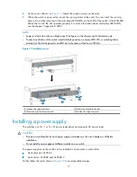
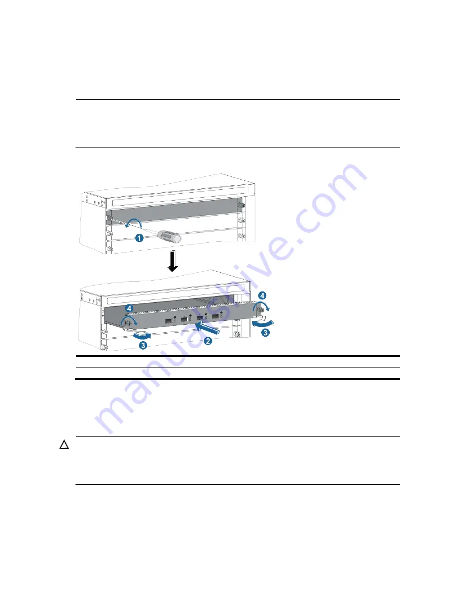
As shown in callout 4 on
Figure 17
, fasten the captive screws on the card.
9.
When the switch is powered on, check the running status of the card. You can check the running
status of a card by referring to the card status LED (SLOT) on the MPU of the switch. If the RUN LED
blinks, the card in the slot operates properly. For more information about card status LED (SLOT),
see the chapter “Appendix C LEDs.”
NOTE:
•
Some card slots do not have a blank panel. The figures in this chapter are for illustration only.
•
To ensure ventilation of the switch, install a blank panel (on an empty MPU, LPU, or switching fabric
module slot. The blank panel for an MPU slot is the same as that for an LPU slot.
Figure 15
Installing a card
(1) Loosen the captive screws
(2) Insert the card into the slot
(3) Press the ejector levers inward
(4) Fasten the captive screws
Installing a power supply
The switches use N + 1 or N + N power redundancy and supports AC power input.
CAUTION:
•
Provide a circuit breaker for each power supply and make sure the circuit breaker is off before
installation.
•
Do not install power supplies of different models on one switch.
The power supplies on the switch can be installed in horizontal or vertical slots.
•
Horizontal slot: A10504
•
Vertical slot: A10508 and A10508-V
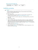
Strictly follow the order shown in
Figure 18
to avoid possible danger.


