Chapter 2
2-1
Site Requirements
2
Site Requirements
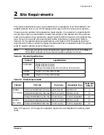
This chapter describes the site requirements for the installation of an HP A1896A or HP
A1897A cabinet. There is no HP site preparation required for the rack-mount cabinets.
There are some customer site preparation requirements. The customer is responsible for
having the proper type and amount of electrical outlets at the cabinet site. The customer
must also be aware of any system site requirements that the computer in the cabinet may
have. Be sure to check all site requirements before installing any equipment. Refer to
Table 2-1 for the cabinet physical specifications, and Table 2-2 for the cabinet electrical
requirements. Table 2-1 shows the types of receptacles that are needed to match the power
cords for specific cabinet power configurations.
NOTE
There are no special environmental site requirements for the HP A1896A or
HP A1897A cabinets, or the computer systems contained in them.
Table 2-1 Physical Specifications
Table 2-2 Power Requirements
Refer to Figure 2-1 for the type of receptacle required to accommodate the cabinet power
cords.
Cabinet
specifications
All Models
Width: 600 mm (23.6 in)
Depth: 905 mm (35.6 in)
Cooling and access space: 610 mm (24 in), front and rear
A1897A
Height: 1.6 meter (63.8 inches)
A1896A
Height: 1.1 meter (44.3 inches)
Cabinet
PDU V/A
Plug Type
Receptacle Type
# IEC 320
Outlets
A1896A
(1.1 meter)
US 100-129V/50/60HZ, 16A max
NEMA 5-20P
NEMA 5-15
6
US 208-240V/50/60Hz, 16A max
NEMA L6-20P
NEMA L6-20R
10
Europe 230V/50/60Hz, 16A max
Cable no plug
Country dependent
10
A1897A
(1.6 meter)
US 208-240V/50/60Hz,16A max
NEMA L6-20P
NEMA L6-20R
10
Europe 230V/50/60Hz,16A max
Cable no plug
Country dependent
10
Summary of Contents for A1896A
Page 10: ...1 4 Chapter1 Introduction Required Tools ...
Page 24: ...4 4 Chapter4 Cabinet Operation Turning Off the Computer System With UPS ...
Page 26: ...5 2 Chapter5 Removal and Replacement Procedures Figure 5 2 Cabinet Exploded View Rear ...
Page 36: ...5 12 Chapter5 Removal and Replacement Procedures Removal and Replacement Procedures ...
Page 43: ...Chapter 6 6 7 System Servicing Rack Mount Assemblies Figure 6 5 Rack Mount Kit Assemblies ...
Page 44: ...6 8 Chapter6 System Servicing Rack Mount Assemblies ...

