background image

1-2

Chapter 1

Introduction

Cabinet Configurations

Cabinet Configurations

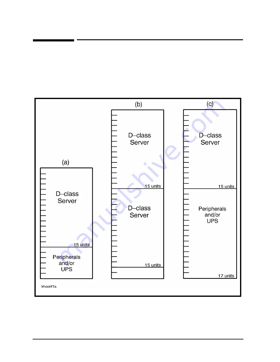
Although the cabinets are designed to accommodate a variety of components mounted in
just about any configuration, there are some basic rules that apply to mounting a computer
system. These rules allow for weight distribution, accessibility of the components, and
cable management inside the rack-mount cabinet. Figure 1-1shows some example
configurations.

Figure 1-1 Cabinet Configuration Examples

Summary of Contents for A1896A

Page 1: ...HP A1896A and HP A1897A Cabinet Installation Guide for HP 9000 D Class Enterprise Servers Part No A3262 90012 Edition 2 August 1997 E0897 Printed in USA ...

Page 2: ...rnment is subject to restrictions as set forth in subparagraph c 1 ii of the Rights in Technical Data and Computer Software clause at DFARS 252 227 7013 for DOD agencies and subparagraphs c 1 and c 2 of the Commercial Computer Software Restricted Rights clause at FAR 52 227 19 for other agencies HEWLETT PACKARD COMPANY 3000 Hanover Street Palo Alto California 94304 U S A Copyright Notices copyrigh...

Page 3: ...ition August 1997 NOTE Reader Comments We welcome your comments about our documentation If you have editorial suggestions or recommended improvements for this document please write to us You can reach us through e mail at hardwaredocs cup hp com or by sending your letter to Documentation Manager M S 5657 Hewlett Packard Company 8000 Foothills Blvd Roseville CA 95747 6588 USA Please include the fol...

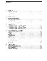
Page 4: ...m Without UPS 4 1 Turning On the Computer System with UPS 4 2 Turning Off the Computer System Without UPS 4 2 Turning Off the Computer System With UPS 4 3 5 Removal and Replacement Procedures Removal and Replacement Procedures 5 4 Rear Door 5 4 Top Cap 5 4 Side Cover 5 5 Forehead Assembly 5 5 Base Cover 5 6 Rear Door Hinge 5 6 Fan Assembly 5 7 Fan 5 8 PDU 5 9 Cabinet Leveler or Caster 5 9 Lock and...

Page 5: ...ving Shipping Clamp 3 4 Figure 3 4 Removing the Shipping Block 3 5 Figure 5 1 Cabinet Exploded View Front 5 1 Figure 5 2 Cabinet Exploded View Rear 5 2 Figure 5 3 Fan Assembly 5 7 Figure 5 4 Fan Diagram 5 8 Figure 6 1 Removing the front bezel 6 1 Figure 6 2 Opening the pivot support bracket 6 2 Figure 6 3 Support Brackets 6 3 Figure 6 4 Positioning the System 6 4 Figure 6 5 Rack Mount Kit Assembli...

Page 6: ...Tables vi Table 2 1 Physical Specifications 2 1 Table 2 2 Power Requirements 2 1 Table 5 1 Rack mount Cabinet Replaceable Parts 5 3 ...

Page 7: ...r s agent be present when the cabinet is unpacked Refer to the instructions described in the Claims Procedure section If everything appears to be in satisfactory condition proceed with the unpacking instructions NOTE Do not discard or destroy the shipping container or the packaging material If it becomes necessary to repackage the cabinet these items will be needed HP also suggests that you keep t...

Page 8: ... of components mounted in just about any configuration there are some basic rules that apply to mounting a computer system These rules allow for weight distribution accessibility of the components and cable management inside the rack mount cabinet Figure 1 1shows some example configurations Figure 1 1 Cabinet Configuration Examples ...

Page 9: ...ls Required Tools Before beginning the installation process make sure you have the necessary tools 1 Standard hand tools including Torx drive set and voltmeter 2 Flat blade screwdriver 3 16 inch by 9 inches long 3 Open ended 9 16 inch wrench ...

Page 10: ...1 4 Chapter1 Introduction Required Tools ...

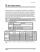
Page 11: ...tch the power cords for specific cabinet power configurations NOTE There are no special environmental site requirements for the HP A1896A or HP A1897A cabinets or the computer systems contained in them Table 2 1 Physical Specifications Table 2 2 Power Requirements Refer to Figure 2 1 for the type of receptacle required to accommodate the cabinet power cords Cabinet specifications All Models Width ...

Page 12: ...f the PDU cable It is the responsibility of the customer to supply the correct plug and receptacle for the particular country and electrical code or have the power cord wired to the power outlet Figure 2 1 Receptacle Types CAUTION Ensure external power connection matches voltage settings of all products in this cabinet ...

Page 13: ...t It is the customer s responsibility to inspect the shipping package for shipping damage It is the Hewlett Packard Customer Engineer s responsibility to remove the cabinet assembly from the shipping pallet NOTE Do not discard or destroy the shipping container or the packaging material If it becomes necessary to repackage the cabinet these items will be needed HP also suggests that you keep this m...

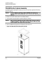
Page 14: ...mately 362 8 kg 800 lbs Be very careful when unpacking the cabinet To unpack an A series cabinet perform the following steps 1 Cut the plastic polystrap bands around the shipping container WARNING Wear protective glasses while cutting the plastic bands around the shipping container These bands are under tension When cut they can spring back and cause serious eye injury 2 Lift the cardboard top cap...

Page 15: ... 4 Remove the ramp and packing material 1 from the top of the cabinet See Figure 3 2 Figure 3 2 Removing the Ramp and Packing Material 5 Remove the shrink wrap 2 from around the cabinet This also holds the bezel protective packing 3 on the front corners of the cabinet Remove the bezel corner packing 3 See Figure 3 2 ...

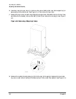
Page 16: ... Then close the rear door 7 Remove the two one on each side shipping clamps from the bottom of the frame They are bolted to the pallet remove the bolt 1 and then remove the clamp 2 See Figure 3 3 Figure 3 3 Removing Shipping Clamp 8 Remove the pallet shipping block 2 from the rear of the pallet Remove the two bolts 1 one on each corner and pull the block 2 out from under the cabinet See Figure 3 4...

Page 17: ... This holds the ramp in place while the cabinet is moved across the pallet and down the ramp See Figure 3 4 10 Raise the cabinet leveling feet to their highest position WARNING Make sure that the leveling feet on the cabinet are raised before you roll the cabinet down the ramp If the leveling feet are not raised they can catch on the ramp and cause the cabinet to tip over 11 Carefully roll the cab...

Page 18: ...g screws for tightness 4 Check all components for signs of shifting during shipment or any signs of damage If any damage is found follow the claims procedures described in Chapter 1 Some damage may be repaired by replacing a damaged part if that part is replaceable Refer to Chapter 5 for a list of field replaceable parts for the cabinet For internal component damage refer to the Service Manual for...

Page 19: ...1 8383 Once all the procedures listed in the UPS guide are complete perform the following steps to complete the UPS installation with the cabinet 1 Position the UPS next to the cabinet on the floor 2 Remove the jumper cord from the SPU to the PDU inside the cabinet 3 Install one of the convenience cords output cord that came with the UPS into the AC receptacle in the back of the SPU 4 Place the ot...

Page 20: ...llet Contact your local Hewlett Packard Sales and Support Office regarding shipment To repackage the cabinet follow the repacking checklist and refer to the unpacking instructions for detail Repacking Checklist 1 Assemble the HP packing materials that came with the cabinet 2 Connect the loading ramp to the pallet 3 Raise the cabinet levelers before moving the cabinet 4 Push the cabinet up the ramp...

Page 21: ... concerning the operating system software for your computer CAUTION Ensure external power connection matches voltage setting of all products in this cabinet 1 Turn on all the external equipment connected to the computer first 2 Check all READY or ONLINE indicators on the external equipment to be sure that they are powered up and ready NOTE If any of the external equipment has been OFF due to envir...

Page 22: ...n the ON position Leave the SPU ON OFF switch in the OFF position 4 When all external equipment indicates READY or ONLINE put the cabinet ON OFF switch in the ON position All components mounted in the cabinet are going to power up at the same time except for the SPU 5 Put the UPS Output switch in the ON position This applies power to the SPU and console line cords 6 Put the SPU and console switche...

Page 23: ...ll be turned off This does not turn off the computer 1 Put the computer power switch in the OFF position 2 Put the console power switch in the OFF position 3 Put the UPS Output switch in the OFF O position 4 Put the cabinet power switch in the OFF position This removes AC from all the components mounted in the cabinet except the computer 5 At this point other components in the cabinet can be turne...

Page 24: ...4 4 Chapter4 Cabinet Operation Turning Off the Computer System With UPS ...

Page 25: ... accomplishing the replacement of a damaged part Refer to Figure 5 1 for an exploded view of the cabinet and Table 5 1 for a list of the cabinet parts that can be replaced if damaged The A1896A cabinet does not come with a fan assembly Otherwise the procedures for parts removal and replacement are the same Refer to Figure 5 1 and Figure 5 2 while performing the procedures outlined in this chapter ...

Page 26: ...5 2 Chapter5 Removal and Replacement Procedures Figure 5 2 Cabinet Exploded View Rear ...

Page 27: ...81 8713 On Off Switch 120V 5181 8714 On Off Switch 220V 9 C2786 00014 Base cover 1 6 meter 11 C2786 60018 Rail assembly C2786 00019 Rear Stop Bracket 12 C2786 60024 230V Fan assembly 3160 0378 230V Fan 13 C2786 60005 115V Fan assembly 3160 0228 115V Fan 14 E4456 63001 US 208 240V PDU 1 6 meter 15 E4457 63001 INT L 230V PDU 1 6 meter 18 C2786 00021 PDU Support Bracket 19 1492 0159 Caster 0535 0096 ...

Page 28: ...rear door by the support column in an open position 2 Align the door hinge pins over the cabinet hinge holes 3 Lower the door onto the cabinet hinge 4 Reconnect the bonding wire to the door Top Cap Refer to Figure 5 1 while performing these procedures Top Cap Removal 1 Turn the cabinet power switch off and unplug the cabinet power cord 2 Open the rear door all the way 3 Remove the two outside moun...

Page 29: ... the left and right edges and align it with the cabinet at an angle with the bottom out and the top toward the top of the cabinet 2 Lower the side onto the top edge of the cabinet side so the top of the side cover hooks onto the top of the cabinet 3 With the side cover flush with the cabinet frame insert the two mounting screws in the bottom Tighten the screws 4 On the right side cover insert the ...

Page 30: ...unting screw located on the top edge center of the base cover 2 Pull the base cover away from the bottom of the cabinet Base Cover Replacement 1 Align the base cover hooks on the bottom of the cabinet frame and roll the base cover until the mounting holes in the cabinet and base cover align 2 Insert the mounting screw Tighten the screw Rear Door Hinge Refer to Figure 5 1 while performing these pro...

Page 31: ...ne mounting screw at the top rear cabinet frame bar 5 Grasp the fan assembly from the bottom and pull toward the rear of the cabinet 6 The fan assembly should release from the cabinet and can be lowered out of the cabinet Fan Assembly Replacement 1 Raise the fan assembly into the rear cabinet frame opening 2 Slide the fan assembly forward engaging the tabs on the fan assembly into the slots in the...

Page 32: ... fan tray Fan Replacement 1 Position the fan over the fan bracket tray mounting holes so that the power lugs are at the rear of the fan tray and on the right side of the fan as viewed from the back of the assembly Also verify the air flow arrow points up 2 Insert the mounting screws up through the bottom of the fan tray bracket and fan 3 Attach mounting nuts washers on the mounting screw Tighten s...

Page 33: ...ket hooks from the frame column 9 Pull the PDU out of the cabinet NOTE The PDU mounting brackets could be removed at this point if necessary PDU Replacement 1 Align the PDU with the brackets attached on the right rear column of the cabinet frame 2 Insert the PDU bracket hooks into the column holes and lower the PDU until it rests on the column 3 Insert the PDU mounting screws through the brackets ...

Page 34: ...or operation Lock and Latch The lock and latch are located in the rear door Lock and Latch Removal 1 Open the rear door 2 Grasp the bracket supporting the lock and latch mechanism 3 Remove the screw and star washer in the center of the bracket The bracket will slide off and the lock and latch mechanism will slide out from the rear door 4 Carefully note the position of the two screws attaching the ...

Page 35: ... by inserting and tightening the screw and star washer Door Bumper The rear door bumpers one top and one bottom are self adhesive rubber bumpers stuck to the rear door To remove pry it off with a flat blade screwdriver To put a bumper on peel off the adhesive cover and press the bumper on the appropriate corner of the rear door ...

Page 36: ...5 12 Chapter5 Removal and Replacement Procedures Removal and Replacement Procedures ...

Page 37: ...rongly recommended that you fully extend the cabinet stabilizer to reduce cabinet instability while servicing the system The cabinet may otherwise overturn and cause damage to the equipment or possible injury 1 Ensure that all power is disconnected from the system 2 Remove the front bezel by grasping the detents on either side and pulling the bezel toward you Refer to Figure 6 1 Figure 6 1 Removin...

Page 38: ...ard you extending the system fully forward on its rails 5 Using a T15 TORX screwdriver remove the three screws in the pivot support bracket refer to callout 2 in Figure 6 2 6 Swing the pivot support bracket around to the right and secure it by pressing it against the fixed support bracket The pivot support bracket will click into place Figure 6 2 Opening the pivot support bracket 7 To access the i...

Page 39: ... cabinet for further servicing follow these steps 1 Remove any cables attached to the rear of the system NOTE Tag the cables if necessary 2 Remove the three screws shown by callout 1 in Figure 6 3 Remove the pivot support bracket 3 Remove the eight screws shown by callout 2 in Figure 6 3 Remove the fixed support bracket Figure 6 3 Support Brackets ...

Page 40: ... component chassis see Figure 6 4 Figure 6 4 Positioning the System 5 Lift and remove the system from the base assembly CAUTION The system weighs as much as 100 lbs and may cause strain if lifted by one person Use two people to lift and remove the system 6 Perform additional servicing as required 7 Replace the system in the cabinet see System Replacement ...

Page 41: ...e system 3 Secure the fixed support bracket with the eight screws as shown in callout 2 of Figure 6 3 4 Secure the pivot support bracket with the three screws as shown in callout 1 of Figure 6 3 5 Replace the three screws along the rear of the assembly refer to Figure 6 4 6 Attach any new or previously detached cables to the system NOTE Attaching the cables while the rails are extended fully forwa...

Page 42: ...2 60028 Slide Rail Assembly Right A3262 60029 Slide Rail Assembly Left A3262 60032 Bottom Bracket Assembly A3262 00060 Top Bracket A3262 00062 Short Ballast A3262 60036 Rack Bezel Assembly Depicted in Figure 6 1 Hardware and Miscellaneous 3020 0042 3 8 16 X 4 Bolt 2 2190 0762 Flat Washer 2 2190 0929 Lock Washer 2 0590 0804 Tinnerman Nut 16 2680 0278 10 32 Screw 14 2680 0323 10 32 Screw 2 0624 0719...

Page 43: ...Chapter 6 6 7 System Servicing Rack Mount Assemblies Figure 6 5 Rack Mount Kit Assemblies ...

Page 44: ...6 8 Chapter6 System Servicing Rack Mount Assemblies ...

Reviews: