


Chapter 4
4-13
Removal and Replacement Procedures
Removal and Replacement Procedures
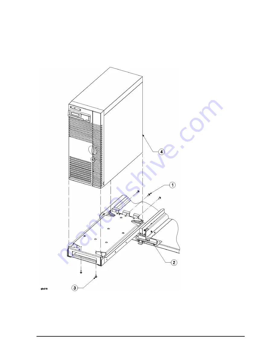
6. Refer to Figure 4-6. Move the computer lockout slide
(2)
away from the front of the
computer, this inhibits all other computers in the cabinet from being extended. Fully
extend the computer on the slide rails.
Figure 4-6 D Class Computer Removal Diagram
7. From under the tray, remove the two tray mounting screws
(3)
, that hold the front of the
computer to the tray. Be sure the three back mounting screws
(1)
are removed.
8. Lift the D Class computer
(4)
off the tray and shelf assembly.
Summary of Contents for A3764A
Page 4: ...iv Contents ...
Page 6: ...vi Figures ...
Page 7: ...Tables vii Table 4 1 A3764A and A3765A Cabinet Replaceable Parts 4 4 ...
Page 8: ...viii Tables ...
Page 10: ...Preface ii ...
Page 14: ...Preface vi ...
Page 18: ...1 4 Chapter1 Introduction Installation Site Requirements ...
Page 28: ...2 10 Chapter2 Unpacking and Installation Repackaging the Cabinet for Shipment ...
Page 32: ...3 4 Chapter3 Cabinet Operation Turning Off the Computer System With UPS ...
Page 34: ...4 2 Chapter4 Removal and Replacement Procedures Figure 4 1 Cabinet Exploded View Front ...
Page 35: ...Chapter 4 4 3 Removal and Replacement Procedures Figure 4 2 Cabinet Exploded View Back ...
Page 56: ...4 24 Chapter4 Removal and Replacement Procedures Removal and Replacement Procedures ...
Page 59: ...Chapter 5 5 3 Computer Access Button up Procedures ...
Page 60: ...5 4 Chapter5 Computer Access Button up Procedures ...


