


Chapter 4
4-15
Removal and Replacement Procedures
Removal and Replacement Procedures
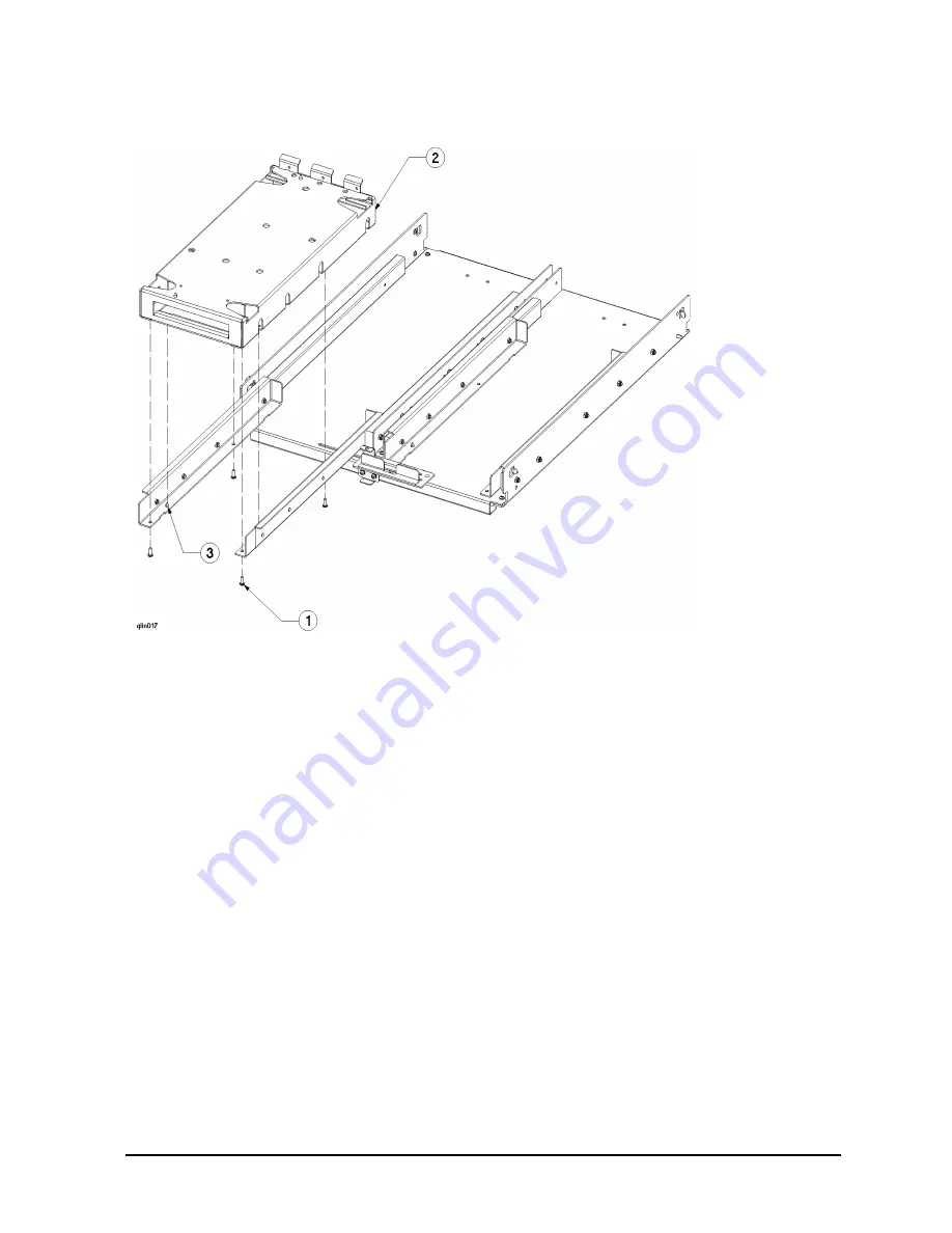
Figure 4-7 Computer Tray Diagram
Computer Tray Replacement:
1. Align tray over the fully extended L bracket and slide assembly guide pins
(3)
, and
lower into place.
2. From underneath the tray
(2)
, insert the four mounting screws
(1)
and tighten.
3. Install D Class computer onto the tray and slide assembly (refer to D Class computer
replacement instructions).
Computer Lock out Assembly
There can be two computer lock out assemblies (one upper and one lower) in a 4 computer
cabinet. These assemblies are inter-connected by a safety rod to allow one computer to be
extended at a time. The computer lock out assembly is a manual device and should be
centered during normal cabinet operation.
Computer Lock Out Assembly Removal:
1. Refer to Figure 4-8. From the top lock out assembly, remove the center slide and
mounting screw
(1)
and lift off the lock out slide.
Summary of Contents for A3764A
Page 4: ...iv Contents ...
Page 6: ...vi Figures ...
Page 7: ...Tables vii Table 4 1 A3764A and A3765A Cabinet Replaceable Parts 4 4 ...
Page 8: ...viii Tables ...
Page 10: ...Preface ii ...
Page 14: ...Preface vi ...
Page 18: ...1 4 Chapter1 Introduction Installation Site Requirements ...
Page 28: ...2 10 Chapter2 Unpacking and Installation Repackaging the Cabinet for Shipment ...
Page 32: ...3 4 Chapter3 Cabinet Operation Turning Off the Computer System With UPS ...
Page 34: ...4 2 Chapter4 Removal and Replacement Procedures Figure 4 1 Cabinet Exploded View Front ...
Page 35: ...Chapter 4 4 3 Removal and Replacement Procedures Figure 4 2 Cabinet Exploded View Back ...
Page 56: ...4 24 Chapter4 Removal and Replacement Procedures Removal and Replacement Procedures ...
Page 59: ...Chapter 5 5 3 Computer Access Button up Procedures ...
Page 60: ...5 4 Chapter5 Computer Access Button up Procedures ...


