


Chapter 4
4-17
Removal and Replacement Procedures
Removal and Replacement Procedures
Shelf Assembly
The shelf assembly has the middle rails and slides attached to the shelf plate. To remove
and replace either the upper or lower the shelf assembly, perform the following steps.
Shelf Assembly Removal:
1. Remove the D Class computer (refer to D Class Computer Removal instructions).
2. Remove the computer tray (refer to Computer Tray Removal).
3. Remove the computer lock out assembly (refer to Computer Lock Out Assembly
removal).
4. Be sure the side rail and slides are fully pushed back into the cabinet for front shelf
assembly mounting screw access.
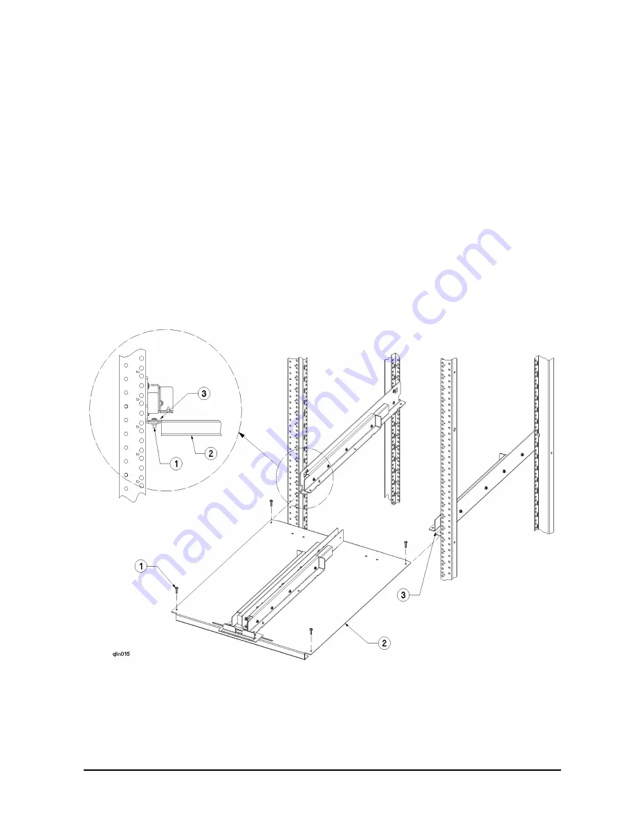
5. Refer to Figure 4-9. Remove the four (one at each corner) shelf assembly mounting
screws
(1)
. These screws hold the shelf assembly
(2)
to the side rail assemblies
(3)
.
Figure 4-9 Shelf Assembly Diagram
6. From the front of the cabinet, slide the shelf assembly
(2)
out of the cabinet. Note the
shelf fits in a slot
(3)
between the lower lip and upper part of the rail and slide assembly.
Summary of Contents for A3764A
Page 4: ...iv Contents ...
Page 6: ...vi Figures ...
Page 7: ...Tables vii Table 4 1 A3764A and A3765A Cabinet Replaceable Parts 4 4 ...
Page 8: ...viii Tables ...
Page 10: ...Preface ii ...
Page 14: ...Preface vi ...
Page 18: ...1 4 Chapter1 Introduction Installation Site Requirements ...
Page 28: ...2 10 Chapter2 Unpacking and Installation Repackaging the Cabinet for Shipment ...
Page 32: ...3 4 Chapter3 Cabinet Operation Turning Off the Computer System With UPS ...
Page 34: ...4 2 Chapter4 Removal and Replacement Procedures Figure 4 1 Cabinet Exploded View Front ...
Page 35: ...Chapter 4 4 3 Removal and Replacement Procedures Figure 4 2 Cabinet Exploded View Back ...
Page 56: ...4 24 Chapter4 Removal and Replacement Procedures Removal and Replacement Procedures ...
Page 59: ...Chapter 5 5 3 Computer Access Button up Procedures ...
Page 60: ...5 4 Chapter5 Computer Access Button up Procedures ...


