background image

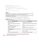
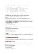
|<0> Exit

|

=========================================================================

Enter your choice(0-4):

You can set the file attribute to M (main) or B (backup), or cancel the setting by selecting a
choice from

1

to

4

.

In this example,

1

is selected and the system changes the file

startup.cfg

from type N/A to type

M.

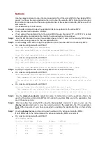
Set the file attribute success!

Now, the attribute of the file

startup_bak1.cfg

has automatically changed from M to N/A.

After selecting

3

from the file control sub-menu, if you select

0

to exit the menu, the system

enters the default mode for the main and backup configuration files, namely the files
cfa0:/main.cfg and/or cfa0:/backup.cfg, if any, are automatically assigned the M and/or B
attributes respectively.

Setting configuration file attributes at the CLI

You can use the

startup saved-configuration

cfgfile

[

backup

|

main

] command to define the

configuration file to be used for the next boot and its attribute. In this command, use

cfgfile

argument to specify the configuration file name.
Note that:

You can use the

startup saved-configuration

cfgfile

main

command to change the attribute of

an N/A-type configuration file to M.

You can use the

startup saved-configuration

cfgfile

backup

command to change the

attribute of an N/A-type configuration file to B.

You can use the

startup saved-configuration

cfgfile

backup

command to change the

attribute of an M-type configuration file to M + B.

You can use the

startup saved-configuration

cfgfile

main

command to change the attribute of

a B-type configuration file to M + B.

If you use neither

main

nor

backup

in your command, you assign the M attribute to the

specified configuration file.

If you assign the M attribute to a configuration file, the attribute of the existing main

configuration file, if any, is automatically erased, because there can be only one main
configuration file in the system at a time.

If you assign the B attribute to a configuration file, the attribute of the existing backup

configuration file, if any, is automatically erased, because there can be only one backup
configuration file in the system at a time.

You can use the

undo startup saved-configuration

command to erase the main and backup

attributes of the configuration files. Namely, the system has no longer a main, nor a backup
configuration file after this command.
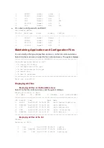
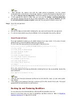
# Define the file startup.cfg as the backup configuration file for the next system boot.

<HP> startup saved-configuration startup.cfg backup

Please wait......Done!

For details about the

startup saved-configuration

cfgfile

command, refer to

File System

Management

in the

System Volume

of

HP SR6600 Routers User Manual.

Deleting a File

Deleting a file on the BootWare menu

Select

3

from the file control sub-menu. The following information appears:

Summary of Contents for A6604

Page 1: ...HP A6604 and A6608 Router Installation Manual ...

Page 2: ... A6604 A6608 including device startup power on and initialization of system files and so on 5 Maintaining Software Introduces how to maintain the software of the HP A6604 A6608 including upgrading the software and updating the configuration files 6 Maintaining Hardware Introduces how to maintain the hardware of the HP A6604 A6608 7 Troubleshooting Describes some problems that may occur during inst...

Page 3: ...K Window names menu items data table and field names are inside square brackets For example pop up the New User window Multi level menus are separated by forward slashes For example File Create Folder Symbols Convention Description Means reader be extremely careful Improper operation may cause bodily injury Means reader be careful Improper operation may cause data loss or damage to equipment Means...

Page 4: ...anual introduces all kinds of interface modules that SR6600 routers support the means of connection the interface cables and the interface module purchase guide Low End and Mid Range Series Routers Cable Manual This manual introduces all cable pinouts available with low end and mid range series routers Environmental Protection This product has been designed to comply with the requirements on envir...

Page 5: ... can work together with other HP network devices to provide full network solutions for carriers and departments in electric power finance tax public security railway and education as well as for medium and large sized enterprises The full compliance with national and international standards ensures the interoperability with the products of other manufacturers at different layers The A6604 and A660...

Page 6: ...ils about the slot arrangement refer to Chapter 2 Arranging Slots and Numbering Interfaces For details about installation and removal of HIMs and MIMs refer to Chapter 4 Installing the Router Physical Description Front View Figure 1 1 Front view of the A6604 configured with an RPE X1 1 Left mounting bracket 2 MPU slot Slot 1 3 RPE X1 Slot 0 4 Right mounting bracket 5 Chassis handle 6 Fan tray 7 AC...

Page 7: ...en 10 FIP slot Slot 3 11 FIP 210 Slot 2 RSE X1 compatible 12 Cable management bracket Figure 1 3 Front view of the A6608 configured with an RPE X1 1 Left mounting bracket 2 MPU slot Slot 1 3 RPE X1 Slot 0 4 Right mounting bracket 5 Chassis handle 6 Fan tray 7 AC power module PWR 1 8 PoE power module reserved 9 Power module PWR 2 10 ESD socket and silkscreen 11 FIP slot Slot 5 12 FIP slot Slot 4 13...

Page 8: ...e PWR 1 7 PoE power module reserved PoE slot 8 Power module PWR 2 9 ESD socket and silkscreen 10 FIP slot Slot 5 11 FIP slot Slot 4 12 FIP 210 Slot 3 13 FIP slot Slot 2 RSE X1 compatible 14 Cable management bracket Currently the device does not support power over Ethernet PoE Rear View Figure 1 5 Rear view of the A6604 1 Warning label 2 Handle on the rear chassis panel ...

Page 9: ... 7 Weight bearing warning label 50 kg or 110 23 lb 8 Grounding screw and sign 9 Vents Do not hold the handle indicated by 2 in Figure 1 5 on the rear chassis panel to move the chassis because it is designed for the convenience of the rear chassis panel removal but not for bearing the chassis weight System Specifications Dimensions Weight and LPU Slots Table 1 2 Dimensions weight and LPU slots Item...

Page 10: ...rovided The power modules must have the same specifications Power consumption range A6604 75 9W 341 2W A6608 86 4W 559W Online insertion and removal Supported Online insertion and removal of a power module refers to first switching off the power module and then removing it from the chassis or inserting it into the chassis Before doing that make sure that the router is configured with redundant pow...

Page 11: ... fan tray Fan built in Specification A6604 A6608 Rated voltage 12 VDC Total fan power consumption 30 W Automatic fan speed adjustment Supported Fay tray dimensions H W D 136 4 31 427 8 mm 5 37 1 22 16 84 in 228 31 413 3 mm 8 98 1 22 16 27 in Failsafe Supported Hot swapping Supported Table 1 6 Description of fan tray LEDs LED Status Meaning RUN green Off The system is powered off or the fan tray is...

Page 12: ...componentized architecture and effectively encapsulates and masks different operating systems and hardware The Comware V5 software platform is the basis of all series of IP network products of HP MPU RPE X1 Front view Figure 1 9 Front view of RPE X1 1 Captive screw 2 Ejector lever 3 RESET button RESET 4 Run LED RUN 5 Active LED of the RPE X1 ACT 6 Alarm LED ALM 7 Link state data reception transmis...

Page 13: ...d for storing the boot file the BootWare program The memory is used for storing the data during system operation and caching the data during data forwarding The non volatile random access memory NVRAM is used for storing the exception information of the system during operation A CF card is used for storing programs and configuration files of the device Hot swapping a module refers to first using t...

Page 14: ...mmediately management Ethernet interface LED LINK ACT yellow green Solid yellow A 10 100 Mbps link is present Solid green A 1000 Mbps link is present Blinking yellow Data is being received or transmitted at a rate of 10 100 Mbps Blinking green Data is being received or transmitted at a rate of 1000 Mbps USB 1 LED USB green Off No host is connected to the device mode USB interface On A host is conn...

Page 15: ... 1 10 Technical specifications for the RSE X1 Item Specification Processor MIPS 1GHz Number of processor cores 2 Flash 4 MB Memory type and size DDR2 SDRAM 2 GB default two memory modules 2 GB maximum NVRAM 128 KB Console port 1 9600 bps to 115200 bps 9600 bps by default AUX port 1 9600 bps to 115200 bps 9600 bps by default Management Ethernet interface 1 10Base T 100Base TX 1000Base T CF card 256...

Page 16: ...ng 8 Hz The application software is being loaded in this case never power off the device or hot swap the RSE X1 otherwise the RSE X1 may be damaged ACT green Off The RSE X1 is in the standby state On The RSE X1 is in the active state ALM red Off The system is operating normally and there is no alarm On A fault has occurred to the system In this state you need to check the system log immediately Fa...

Page 17: ...sh size is 4 MB of which 1 MB is used for storing the boot file BootWare and the remaining space for BootWare backup and important system parameters Memory module The memory module is used for storing the data exchanged between the system and the CPU The default memory size of an RPE X1 is one GB memory and the maximum memory size is two GB One RPE X1 provides two memory slots in which you can ins...

Page 18: ... debugging configuration maintenance management and host software loading 2 Technical specifications for the console port Table 1 12 Technical specifications for the console port Item Specification Connector RJ 45 Compliant standard Asynchronous EIA TIA 232 Baud rate 9600 bps to 115200 bps 9600 bps default Transmission Distance 15 m 49 21 ft Services Connection to an ASCII terminal Connection to t...

Page 19: ... remote modem through PSTN and then to the remote device for remote system debugging configuration maintenance and management In the event that the console port fails the AUX port can be connected to a terminal as a backup port of the console port For details refer to Using the Port AUX as Backup Console Port in Chapter 7 Troubleshooting Technical specifications for the AUX port Technical specific...

Page 20: ...AUX cable connectors AUX cable connector pinouts Signal direction DB 25 pin DB 9 pin 4 7 20 4 2 3 8 1 7 5 3 2 6 6 5 8 For the connection of the AUX cable refer to Connecting the AUX Port to a Modem in Chapter Universal serial bus USB interfaces can connect multiple types of devices and provide a higher data transfer rate than common parallel interfaces and serial interfaces The device fully suppor...

Page 21: ... the umount command refer to File System Management in the System Volume of HP SR6600 Routers User Manual 2 USB 1 and LED USB interface 1 on the device is a USB 1 1 compliant type B interface USB interface 1 can be connected to a host device through a standard USB cable The host recognizes the device as an external storage device so that you can access the internal CF card quickly and perform file...

Page 22: ... date and time For the description of the clock datetime command refer to Basic System Configuration in the System Volume of HP SR6600 Routers User Manual When a power failure occurs to the router the clock module can continue working to ensure the system time is correct next time the router boots With the router powered off the clock module can work for at least 10 years When the router is powere...

Page 23: ...tandby RPE X1 Do not use centralized device specific software to update the router that supports the active standby switchover feature Otherwise the router may become unavailable FIPs FIP 100 Introduction The FIP 100 supports MIMs only It provides high density narrowband aggregation and hence can protect legacy investment The FIP 100 supports four MIMs at the same time Figure 1 17 Front view of th...

Page 24: ...lectrical interface For a Combo interface you can use either the electrical Ethernet interface or the optical Ethernet interface You can use the combo enable copper fiber command in interface view to switch between the optical and electrical interfaces For details about the combo enable copper fiber command refer to Ethernet Interfaces in the Access Volume of HP SR6600 Routers User Manual Use opti...

Page 25: ... FIP 100 is not working SFP0 to SFP1 yellow green Off No optical link is present Solid green An optical link is present Blinking green Data is being sent or received at a rate of 1000 Mbps Solid yellow The optical transceiver failed to be detected GE0 to GE1 yellow green Off No link is present Solid green A 1000 Mbps link is present Blinking green Data is being received or transmitted at a rate of...

Page 26: ...aggregation and hence can protect legacy investment The FIP 110 supports four MIMs at the same time Figure 1 20 Front view of the FIP 110 1 Slot 1 2 Slot 2 3 Slot 3 4 Slot 4 5 OPEN BOOK sign 6 Combo interface 0 7 Combo interface 1 OPEN BOOK sign Refer to related sections when performing the following operations Operation Reference Plug unplug an FIP 110 Installing and Removing an FIP in Chapter 4 ...

Page 27: ...face For a Combo interface you can use either the electrical Ethernet interface or the optical Ethernet interface You can use the combo enable copper fiber command in interface view to switch between the optical and electrical interfaces For details about the combo enable copper fiber command refer to Ethernet Interfaces in the Access Volume of HP SR6600 Routers User Manual Use optical transceiver...

Page 28: ...r hot swap the FIP may be damaged or the FIP 110 is not working Off No optical link is present Solid green An optical link is present Blinking green Data is being sent or received at a rate of 1000 Mbps Solid yellow The optical transceiver has failed in POST Off No link is present Solid green A 1000 Mbps link is present Blinking green Data is being received or transmitted at a rate of 1000 Mbps So...

Page 29: ... HIMs or two MIMs or intermixing of an HIM and an MIM Figure 1 23 Front view of FIP 200 1 Slot 1 2 Slot 2 3 Combo interface 0 4 Combo interface 1 5 OPEN BOOK sign OPEN BOOK sign Refer to related sections when performing the following operations Operation Reference Plug unplug an FIP 200 Installing and Removing an FIP in Chapter 4 Installing the Router Plug unplug an MIM Installing and Removing a M...

Page 30: ...ombo interface you can use either the electrical Ethernet interface or the optical Ethernet interface You can use the combo enable copper fiber command in interface view to switch between the optical and electrical interfaces For details about the combo enable copper fiber command refer to Ethernet Interfaces in the Access Volume of HP SR6600 Routers User Manual Use optical transceivers provided b...

Page 31: ...ram is being loaded in this case never power off the device or hot swap the FIP may be damaged Off No optical link is present Solid green An optical link is present Blinking green Data is being sent or received at a rate of 1000 Mbps Solid yellow The optical transceiver has failed in POST Off No link is present Solid green A 1000 Mbps link is present Blinking green Data is being received or transm...

Page 32: ...210 supports SR6600 HIMs and MIMs and provides two Combo interfaces In consideration of smooth upgrade requirements the FIP 210 supports two HIMs or two MIMs or intermixing of a HIM and a MIM Figure 1 26 Front view of the FIP 210 1 Slot 1 2 Slot 2 3 OPEN BOOK sign 4 Combo interface 1 5 Combo interface 0 OPEN BOOK sign Refer to related sections when performing the following operations Operation Ref...

Page 33: ... For a Combo interface you can use either the electrical Ethernet interface or the optical Ethernet interface You can use the combo enable copper fiber command in interface view to switch between the optical and electrical interfaces For details about the combo enable copper fiber command refer to Ethernet Interfaces in the Access Volume of HP SR6600 Routers User Manual Use optical transceivers pr...

Page 34: ...s being loaded in this case never power off the device or hot swap the FIP may be damaged Off No optical link is present Solid green An optical link is present Blinking green Data is being sent or received at a rate of 1000 Mbps Solid yellow The optical transceiver has failed in POST Off No link is present Solid green A 1000 Mbps link is present Blinking green Data is being received or transmitted...

Page 35: ...al Ethernet interface For the rate and duplex mode when the electrical Ethernet interface is operating see Table 1 29 Table 1 29 Rate and duplex mode when the electrical Ethernet interface is operating Rate Duplex mode 10 Mbps Half full duplex auto negotiation 100 Mbps Half full duplex auto negotiation 1000 Mbps Full duplex The electrical Ethernet interface LEDs are above the RJ 45 ports The LEDs ...

Page 36: ...You can use the combo enable copper fiber command in interface view to switch between the optical and electrical Ethernet interfaces For details about the combo enable copper fiber command refer to Ethernet Interfaces in the Access Volume of HP SR6600 Routers User Manual Technical specifications for Combo interfaces Technical specifications for electrical Ethernet interfaces Table 1 30 Technical s...

Page 37: ...timode optical interface module 850 nm Medium haul single mode optical interface module 1310 nm Long haul Optical interface module 1310 nm Long haul optical interface module 1550 nm Ultra long haul optical interface module Min 9 5 dBm 9 dBm 2 dBm 4 dBm 4 dBm Max 0 dBm 3 dBm 5d Bm 1 dBm 2 dBm Receiving sensitivity 17 dBm 20 dBm 23 dBm 21 dBm 22 dBm Central wavelength 850 nm 1310 nm 1310 nm 1550 nm ...

Page 38: ...ystem debugging and maintenance more convenient and the transit dispatching of the system more flexible Some optical fiber connector types are as follows LC square optical fiber connector of the push pull snap in type SC standard optical fiber connector FC round optical fiber connector with screw thread in optical fiber connector RJ square transceiver optical fiber connector SR6600 routers support...

Page 39: ... 5 White Blue 5 6 Rx Green 2 7 White Brown 7 8 Brown 8 You can refer to the table above when distinguishing between or preparing these two types of Ethernet cables When preparing Ethernet cables please follow the chromatogram given in the table to arrange the wires Otherwise communication quality will be affected even if the equipment at two ends are connected When preparing Ethernet cables use sh...

Page 40: ...P 100 FIP 110 FIP 200 FIP 210 HIM Not supported Not supported Supported Supported MIM Supported Supported Supported Supported State description of the FIP A FIP can be in one of six states as shown in Table 1 35 Table 1 35 State description of FIPs Status Meaning Remarks Absent Out of position No FIP is installed in a slot of the router Disable Powered off through the CLI The user powers off a FIP...

Page 41: ...r you need to install a lightning protection busbar at the AC power input end and then connect the AC power cord to a lightning protection busbar to protect the router against lightning strokes In a heavy lightning area you are recommended to install a power lightning arrester The following power lightning arrester can be installed on the device The specifications for the power lightning arrester ...

Page 42: ...y types of interfaces such as console AUX GigabitEthernet serial synchronous POS and E1 ports This chapter describes how these interfaces are numbered Figure 2 1 Slot arrangement on the A6604 configured with an RPE X1 Figure 2 2 Slot arrangement on the A6604 configured with an RSE X1 ...

Page 43: ...SE X1 The numbers in Figure 2 1 through Figure 2 4 represent corresponding slot numbers On a device configured with an RSE X1 slots are numbered from Slot 1 instead of Slot 0 Slot Arrangement for MPUs and FIPs Table 2 1 Slot arrangement for MPUs MPU Slot arrangement A6604 A6608 RPE X1 supporting 1 1 redundancy Slot 0 and Slot 1 ...

Page 44: ...ber namely the number of the slot where the HIM MIM resides on the FIP Z Sequence number of the interface on the HIM MIM Different interface modules on the same LPU have the same slot number X Different interfaces on the same interface module have the same sub slot number Y For each type of interface the sequence number Z starts from 0 on the interface module For a device configured with the RPE X...

Page 45: ...GBE module is installed on the FIP 110 Numbers of fixed GigabitEthernet interfaces on the FIP 110 GigabitEthernet 3 0 0 GigabitEthernet 3 0 1 Numbers of GigabitEthernet interfaces on the MIM 2GBE module 1 If a MIM 2GBE module is installed in Slot 1 of the FIP 110 the numbers of GigabitEthernet interfaces are GigabitEthernet 3 1 0 GigabitEthernet 3 1 1 2 If a MIM 2GBE module is installed in Slot 2 ...

Page 46: ... 210 Numbers of fixed GigabitEthernet interfaces on the FIP 210 GigabitEthernet 3 0 0 GigabitEthernet 3 0 1 Numbers of GigabitEthernet interfaces on the HIM 4GBE module 1 If a HIM 4GBE is installed in Slot 1 of the FIP 210 the numbers of Gigabit Ethernet interfaces are GigabitEthernet 3 1 0 GigabitEthernet 3 1 1 GigabitEthernet 3 1 2 GigabitEthernet 3 1 3 2 If a HIM 4GBE is installed in Slot 2 of ...

Page 47: ...scharge ESD which may damage the CMOS circuit on the router A high temperature will speed up the aging of insulation materials which greatly lowers the router s reliability and shortens the service life Table 3 1 lists the requirements on temperature and humidity for the device Table 3 1 Temperature and humidity requirements in the equipment room Temperature Relative humidity 0 C to 45 C 32 F to 1...

Page 48: ...and CI2 in the equipment room Table 3 3 Concentration limit of some harmful gases in the equipment room Gas Max mg m 3 SO2 0 2 H2S 0 006 NH3 0 05 Cl2 0 01 Ventilation Requirements The fans of the device draw air in through the inlet vents on the left and out through the exhaust vents on the right The fan tray supports automatic fan speed adjustment and hot swapping To ensure good ventilation make ...

Page 49: ...erface module Place the removed memory module CF card or HIM MIM on an antistatic workbench with the face upward or put it into an antistatic bag Touch only the edges instead of electronic components when observing or moving a removed memory module CF card or HIM MIM Connection of the ESD preventive wrist strap Follow these steps to connect the ESD preventive wrist strap Step1 Put on the ESD preve...

Page 50: ...parate the protection ground of the router from the grounding device or lightning protection grounding device of the power supply equipment as far as possible Keep the router far away from radio stations radar and high frequency devices working in high current Use electromagnetic shielding when necessary Lightning Protection Although many measures have been taken to protect the device from lightni...

Page 51: ... in view of the heavy weight of the router Make sure that the cabinet is sturdy enough to support the weight of the router and installation accessories Make sure that the size of the cabinet is appropriate for the router and that there is enough clearance around the left and right panels of the router for heat dissipation For the sake of heat dissipation and device maintenance it is recommended th...

Page 52: ...ter is powered on Connect the interface cables for the router correctly Use laser with caution Do not directly stare into apertures or fiber optic connectors that emit laser radiation Equip an uninterrupted power supply UPS Disconnect the two power inputs to power off the router if there are two power inputs Avoid maintaining the router alone when it is powered on Installation Tools Meters and Dev...

Page 53: ... prevention Take effective measures to protect the power system from the power grid system Separate the protection ground of the router from the grounding device or lightning protection grounding device as far as possible Keep the router far away from radio stations radar and high frequency devices working in high current Use electromagnetic shielding when necessary Lightning protection The PGND c...

Page 54: ...er is far away from any moist area and heat source The emergency power switch in the equipment room is located Tools Installation accessories supplied with the router User supplied tools Reference Documents shipped with the router Online documents ...

Page 55: ...on in Chapter 3 Preparing for Installation 5 When operating a demountable module such as an RPE X1 a chassis accessory a FIP a memory module a CF card a HIM and a MIM note that Ensure good alignment with the slot and use proper force to avoid damage to the module during installation or removal Avoid touching any components on the PCB during observation or moving Put the removed module on an antist...

Page 56: ...Table 4 1 Dimensions of the device Item remove slot slotnumber and remove slot slotnumber Device Management in the System Volume of HP Installation Flowchart Installation flowchart for the device Router Installation in a Rack Install the router after you have completed the installation preparations Dimensions of the Router The device is designed to fit standard 19 inch racks The following table de...

Page 57: ...g Mounting Brackets onto the Router Before installing the router in a rack you need to install the cable management bracket to the left mounting bracket and fix the left and right mounting brackets to the left and right sides of the router respectively Figure 4 2 shows structure of the mounting brackets Figure 4 2 Structure of mounting brackets 1 Left mounting bracket 2 Right mounting bracket Step...

Page 58: ...4 4 Install the mounting brackets to the A6608 Installing the Router in a Rack Follow these steps to install the router in a rack Step1 Check the grounding and stability of the rack Step2 Install a support tray on the rack for the router Skip this step if a support tray is already installed Step3 Use screws to fix the mounting brackets onto both sides of the front panel of the router Refer to Inst...

Page 59: ...GND Cable Connection Importance of the PGND Cable The correct connection of the protection ground PGND cable on the router chassis is an essential safeguard against the lightning strokes and electromagnetic interference EMI You need to correctly connect the PGND cable when installing or using the router The power input end of the device is equipped with a noise filter The neutral ground of the pow...

Page 60: ...nel Step2 Put the supplied OT terminal of the PGND cable on the grounding screw Step3 Fasten the grounding screw which is attached with the OT terminal of the PGND cable into the grounding screw hole with a screwdriver Step4 Connect the other end of the PGND cable to the ground Generally the cabinets are installed in equipment rooms that are equipped with a grounding bar If a grounding bar is avai...

Page 61: ...st be less than 5 ohms Use the PGND cable provided with the router to connect the ground bar in the equipment room Otherwise the router may not be effectively grounded which easily causes damage to the router Installing and Removing an RPE X1 Interior Structure of an MPU Figure 4 8 Interior structure of the RPE X1 1 Memory module 2 Memory module slot 3 CPU heatsink 4 Built in CF card 5 Release lat...

Page 62: ...cessory to hold the RPE Figure 4 10 Structure of the chassis accessory 1 Positioning holes 3 Power connector Interior structure of the RSE X1 2 Bridge heatsink 1 4 Bus connectors 6 Power connector 8 Release latch Face the front panel of the router Locate the slot where you will install the RPE X1 Slot 0 or Slot 1 the figures below illustrate X1 to Slot 1 to hold the RPE X1 Structure of the chassis...

Page 63: ...e chassis accessory Then push the ejector levers inward to lock the chassis accessory in position and fasten the captive screws on the ejector levers Step5 Gently push the RPE X1 into Slot 1 along the slide rails and then push the ejector levers inward to lock the board in position Figure 4 12 Insert the RPE X1 into the slot Step6 Fasten the captive screws clockwise with a Philips screwdriver Figu...

Page 64: ...PE X1s you can remove one of the RPE X1s when both of them are operating normally To remove the active RPE X1 you are recommended to use the slave switchover command to implement manual active standby switchover in system view of the active RPE X1 For details about this command refer to HA in the System Volume of HP SR6600 Routers User Manual To remove the standby RPE X1 follow steps mentioned bel...

Page 65: ...a Blank Panel on page 4 35 Installing an RSE X1 Step1 Face the front panel of the router Step2 Locate the slot where you will install the RSE X1 Slot 1 or Slot 2 the figures below illustrate how to install an RPE X1 to Slot 1 Step3 Gently push the RSE X1 into Slot 1 along the slide rails and then push the ejector levers inward to lock the board in position Figure 4 16 Insert the RSE X1 into the sl...

Page 66: ...the RSE X1 Online removal of the RSE X1 may cause damages to the RSE X1 FIPs and HIMs MIMs 2 For a device configured with two RSE X1s you can remove one of the RSE X1s when both of them are operating normally To remove the active RSE X1 you are recommended to use the slave switchover command to implement manual active standby switchover in system view of the active RSE X1 For details about this co...

Page 67: ... X1 in the slot install a blank panel to prevent dust from entering the chassis For how to install a blank panel refer to Installing and Removing a Blank Panel on page 4 35 Installing and Removing a FIP Interior Structure of a FIP The router configured with the RPE X1 supports four types of FIPs FIP 100 FIP 110 FIP 200 and FIP 210 The router configured with the RSE X1 supports two types of FIPs FI...

Page 68: ...Release latch 3 Memory module 4 CPU heatsink 5 Memory module slot 6 Bus connectors 7 Power connector Figure 4 21 Interior structure of the FIP 110 1 Positioning holes 2 Release latch 3 Memory module slot 4 Memory module 5 CPU heatsink 6 Bus connectors 7 Power connector ...

Page 69: ... slot 6 CPU heatsink 8 Bus connectors Interior structure of the FIP 210 2 Release latch 3 Memory module slot 4 Memory module 6 Bus connectors to install a FIP 200 You can install FIPs in a similar way Face the front panel of the router Locate the slot where you will install the FIP and remove the blank panel from the position For how to remove a blank panel refer to Installing and Removing a Blank...

Page 70: ... slot then install the FIP and finally install the removed blank panels to prevent dust from entering the chassis Do not insert or remove a HIM MIM into or from a FIP when the RUN LED on the FIP is blinking fast Otherwise an exception may occur By default the RUN LEDs of the FIPs will light up in the ascending order of slot numbers For a device configured with an RPE X1 and a combination of FIPs i...

Page 71: ...o run the undo remove slot slot number command after you remove a FIP and insert it again The following describes how to remove a FIP 200 You can remove FIPs in a similar way Step1 Face the front panel of the router Step2 Locate the FIP to be removed The figures below illustrate how to remove the FIP in Slot 3 Step3 Loosen the captive screws on the FIP counterclockwise with a Philips screwdriver F...

Page 72: ... HIM Step1 Face the front panel of the router Step2 Locate the slot where you will install the HIM Step3 Remove the two blank panels from the position where you will install the HIM For how to remove the blank panels refer to Installing and Removing a Blank Panel on page 4 35 Step4 Gently push the HIM with the components facing upwards into the HIM slot along the slide rails and then push the ejec...

Page 73: ...ully Press Enter The following message appears on the terminal screen System is busy with VIU configuration recovery please wait a moment HP This means the HIM has been successfully installed 2 If the router does not recognize the HIM or if the HIM installation failed the following information appears on the terminal screen HP Apr 26 15 36 09 404 2008 HP DRVICOUT 1 DrvIcOutStr Slot 2 Src Slot 2 Sl...

Page 74: ...un the undo remove slot command after you remove a HIM and insert it again Follow these steps to remove a HIM Step1 Face the front panel of the router Step2 Locate the HIM to be removed Step3 Loosen the two captive screws on the HIM counterclockwise with a flat blade screwdriver Figure 4 30 Loosen the captive screws Step4 Pull the two ejector levers at both ends of the HIM outward to release the H...

Page 75: ...ce the front panel of the router Step2 Locate the slot where you will install the MIM Step3 Remove the blank panel from the position where you will install the MIM For how to remove the blank panels refer to Installing and Removing a Blank Panel on page 4 35 Step4 Gently push the MIM with the components facing left into the MIM slot along the slide rails Figure 4 32 Push the MIM into the slot Step...

Page 76: ...rs on the terminal screen HP Apr 26 15 36 09 404 2008 HP DRVICOUT 1 DrvIcOutStr Slot 2 Src Slot 2 Slot 2 4 Plug In Failed HP The device supports hot swapping of MIMs When installing a MIM use proper force and keep the MIM in the horizontal position to avoid damage to components on the card Removing a MIM Be sure to run the remove slot slot number subslot subslot number command before removing a MI...

Page 77: ...MIM from Sub slot 1 of a FIP make sure that your hand does not intervene with the right ejector lever of the FIP To protect the removed MIM place it in an antistatic bag If you do not install a new MIM in the slot install a blank panel to prevent dust from entering the chassis For how to install blank panels refer to Installing and Removing a Blank Panel on page 4 35 Connecting Interface Cables Co...

Page 78: ...e configuration terminal displays the startup banner of the router if the connection is correct For details refer to Router Power Chapter 5 Starting and Configuring the Router A console cable is connected in the same way for both the A6604 and the A6608 figure shows how to connect a console cable for the A6608 Connect the console cable 2 RJ 45 connector 3 Serial interface on the configuration term...

Page 79: ... and manage the router through a network management server It is not a service interface and therefore it cannot send or receive data onnect the management Ethernet interface to the configuration terminal with a through cable or crossover cable Follow these steps to connect the management Ethernet interface to the configuration terminal Turn off the power switches on all power modules of the route...

Page 80: ...on terminal 9 female connector 9 Ethernet cable Connecting Ethernet Cables Connecting an electrical Ethernet interface Connect one end of an Ethernet cable to an electrical Ethernet interface on the device and the other end to the Ethernet interface on the peer device Because a 10Base T fixed electrical Ethernet interface supports MDI MDIX auto through cable or crossover cable to connect the inter...

Page 81: ...nto the optical SFP transceiver receptacle Figure 4 40 Insert an SFP module Step3 Identify the Rx and Tx ports on the SFP transceiver module Plug the LC connector at one end of one fiber cable into the Rx port of the router and the LC connector at the other end into the Tx port of the peer device Plug the LC connector at one end of another fiber cable into the Tx port of the router and the LC conn...

Page 82: ...he curvature radius less than 10 cm 3 94 in Ensure that the Tx and Rx ports of the SFP transceiver module are connected correctly Keep the end faces of optical fiber cables clean Never stare into an open optical Ethernet interface because invisible rays may be emitted from the optical Ethernet interface Cover the dust cover if no optical fiber connector is connected to the optical Ethernet interfa...

Page 83: ...ower connector with a grounding contact Ground the power supply reliably Normally the grounding contact of the power supply system in a building was buried during construction and cabling Before connecting the AC power cord make sure that the power supply of the building is well grounded Connection procedure Follow these steps to connect the AC power cord Step1 Make sure that the PGND terminal is ...

Page 84: ... cord 1 Bail latch 2 AC power cord 3 AC power socket 4 AC power LED 5 AC power switch 6 Power module handle 7 Captive screw Connecting the DC Power Cords DC power supply Rated voltage range 48 VDC to 60 VDC DC power socket Figure 4 44 illustrates a DC power module in the chassis Figure 4 44 DC power module in the chassis 1 Captive screw 2 DC input terminals 3 DC power switch 4 DC power LED 5 Power...

Page 85: ... DC power cords Step1 Move the power switch on the DC power module to the OFF position Step2 Unscrew the DC input terminals with a Phillips screwdriver Step3 Connect the end marked with of the supplied blue DC power cord to the negative terminal on the power module and fasten the screw Step4 Connect the end marked with of the supplied black DC power cord to the positive terminal on the power modul...

Page 86: ...ot Figure 4 46 Blank panel for an 1 Front view 3 Oblique rear view Figure 4 47 Blank panel for an LPU slot 1 Front view 3 Oblique rear view Four types of blank panels are available in the device X1 slot Blank panel for a HIM MIM slot Blank panel for a power module slot Blank panel for an RPE X1 slot 2 Side view 4 EMI gasket Blank panel for an LPU slot 2 Side view 4 EMI gasket ...

Page 87: ...to remove a FIP blank panel Blank panel for a HIM MIM slot 2 Side view 4 EMI gasket Blank panel for a power module slot 2 Side view 4 EMI gasket Removing a Blank Panel Follow these steps to remove a blank panel Face the front panel of the router Locate the blank panel to be removed X1 FIP power or HIM blank panel loosen the two captive screws counterclockwise with a Philips screwdriver until all s...

Page 88: ...where you will install a blank panel For an RPE X1 FIP or power blank panel Insert the blank panel into the slot and then fasten the captive screws clockwise with a Philips screwdriver For a HIM MIM blank panel Insert the blank panel into the slot and then fasten the fastening screws clockwise with a Philips screwdriver Step3 The following figure illustrates how to install a FIP blank panel Figure...

Page 89: ... if the router is powered off Step5 The power LED green lights up indicating the power module runs normally The device supports online insertion and removal of a power module Online refers to first switching off the power module and then removing it from the router or inserting it into the router Before doing that make sure that the router is configured with redundant power modules and the system ...

Page 90: ... antistatic bag If you do not install a new power module in the slot install a blank panel to prevent dust from entering the chassis For how to install a blank panel refer to Installing and Removing a Blank Panel on page 4 35 Installing and Removing a Fan Tray Fan Tray Structure Figure 4 56 Fan tray on the A6604 1 Run LED RUN 2 Alarm LED ALM 3 Fan 4 Handle 5 CAUTION sign 6 Captive screw ...

Page 91: ...y into the slot Step4 Fasten the captive screws clockwise with a Philips screwdriver Fan tray on the A6608 2 Alarm LED ALM 4 Fan 6 Captive screw Face the front panel of the router Make sure that the CAUTION sign on the fan tray panel is not upside down otherwise the fan tray cannot be inserted into the fan tray slot Gently push the fan tray into the slot along the slide rails Push the fan tray int...

Page 92: ...hot swapping of the fan tray For of description of the fan tray LEDs refer to Table 1 6 in Chapter 1 Router Overview Removing a Fan Tray Keep your hands away from the spinning fan blades when removing the fan tray To remove a fan tray reverse the installation procedure Step1 Face the front panel of the router Step2 Loosen the captive screws on the fan tray counterclockwise with a Philips screwdriv...

Page 93: ...ng a CF Card CF Card and Slot Figure 4 62 CF card and slot 1 Eject button Loosen the captive screws Gently pull the fan tray out along the slide rails Take out the fan tray Do not keep the router working without a fan tray for a long time because poor ventilation may result in damage to the router To protect the removed fan tray place it in an antistatic bag Inserting and Removing a CF Card CF car...

Page 94: ... If the application program for booting the router is stored in an external CF card make sure that the right CF card has been correctly installed in the slot otherwise the router will fail to boot Removing a CF Card Follow these steps to remove a CF card Step1 Check whether the CF card LED is blinking If yes the system is accessing the CF card Proceed to the next step after the LED stops blinking ...

Page 95: ...r FIP refer to Removing a FIP on page 4 19 When to Replace a Memory Module Memory modules are removable components on the main board Generally you need to replace a memory module in the following situations More memory is needed to upgrade the application program The router needs to maintain a large routing table or support other highly memory consuming operations An existing memory module is dama...

Page 96: ...nt flowchart Memory Module and Slot Figure 4 67 Memory module used in the 1 Connector edge 3 Latch notch Memory module replacement flowchart Memory Module and Slot Memory module used in the A6608 2 Polarization notch 2 Polarization notch ...

Page 97: ...emory module directly with your hands Hold the memory module only at its non conductive edge Because a memory module is vulnerable to ESD improper operation may damage it Do not use too much force in the operation To protect the removed memory module place it in an antistatic bag Installing a Memory Module Follow these steps to install a memory module Step1 Locate the card RPE X1 or FIP to which y...

Page 98: ...s dust from entering the chassis Installing an Air Filter Follow these steps to install an air filter Step1 Face the left side of the chassis where the air filter is to be installed Step2 Position the upper slide rail horizontally near the top of the left side of the chassis as shown in Figure 4 71 Align the screw holes on the slide rail with those on the chassis Step3 Fasten the fastening screws ...

Page 99: ...ll the air filter slide rails Step6 Gently push the air filter along the slide rails until it is seated in position Figure 4 72 Insert the air filter Step7 Fasten the captive screws clockwise with a Philips screwdriver ...

Page 100: ... procedure Step1 Face the left side of the chassis where the air filter is to be removed Step2 Loosen the captive screws one by one counterclockwise with a Philips screwdriver until all spring pressure is released Figure 4 74 Loosen the captive screws Step3 Gently pull out the air filter along the slide rails ...

Page 101: ...8 20μs waveform 5 kA output voltage 10 700μs waveform core core 40 V core ground 600 V Tools Phillips or flat blade screwdriver Multimeter Diagonal pliers Installation Procedure Follow these steps to install a port lightning arrester Step1 Use a double faced adhesive tape to stick the port lightning arrester to the router The port lightning arrester should be as close to the grounding screw as pos...

Page 102: ... should be connected to the Ethernet The port lightning arrester is not well grounded Make sure that the grounding cable of t lightning arrester should be as short as possible and be well connected to the grounding screw of the router You need to check with a multimeter after connection The installed port lightning arresters are not sufficient When more than one outdoor Ethernet cable is connected...

Page 103: ...PE terminal of the power lightning arrester is not grounded If the live and zero wires are on the right and left respectively supposing that you are facing the socket the polarity of the power socket of the power lightning arrester is reversed In this case you should open the power socket to correct the polarity After that if the red LED is still ON you can make sure that the PE terminal of the po...

Page 104: ...al cases Connect the grounding cable to the special purpose grounding cable of the signal lightning arrester and connect it to the grounding grid instead of connecting it to the lightning rod or lightning belt Verifying Installation Each time you power on the router during installation you must verify that There is enough space around the router for heat dissipation and the workbench is stable eno...

Page 105: ...er Overview You can perform operations and configurations only on the active RPE X1 The startup and configuration process is the same for both the A6604 and the A6608 no matter whether an RPE X1 or RSE X1 is installed An A6608 configured with an RPE X1 is taken as an example in this chapter Setting Up a Configuration Environment Connecting the Router to a Configuration Terminal For how to connect ...

Page 106: ... to which the console cable is actually connected Figure 5 2 Select a port for local configuration connection Step3 Set serial port parameters Figure 5 3 Set serial port parameters Set the properties of the serial port in the COM1 Properties dialog box as shown in Figure 5 3 Table 5 1 Set serial port parameters Item Value Bits per second 9600 bps default Data bits 8 ...

Page 107: ...ers to enter the HyperTerminal window as shown below Figure 5 4 HyperTerminal window Step5 Set HyperTerminal properties In the HyperTerminal window select File Properties from the menu and select the Settings tab to enter the properties setting dialog box as shown in Figure 5 5 Select VT100 or Auto detect and click OK to return to the HyperTerminal window ...

Page 108: ... card is properly installed Before powering on the router learn where the power switch is located so that you can disconnect the power supply in time in case of an emergency Powering On the Router Turn on the power source Turn on the power switch on the router Checklist Operations after Power on After powering on the router check that 1 The LEDs on the front panel are normal For description of the...

Page 109: ...nformation appears on the terminal screen System start booting Booting Normal Extend BootWare HP SR66 BootWare Version 1 24 Copyright c 2004 2008 Hangzhou HP Technologies Co Ltd Compiled Date Dec 24 2008 CPU Type MPC8548E CPU L1 Cache 32KB CPU Clock Speed 1000MHz Memory Type DDR2 SDRAM Memory Size 1024MB Memory Speed 400MHz BootWare Size 1024KB Flash Size 4MB cfa0 Size 495MB NVRAM Size 128KB BASIC...

Page 110: ...rface con0 is available Press ENTER to get started Press Enter and the screen will display HP This prompt indicates that the router has entered user view and is ready to configure Configuration Fundamentals In general the configuration steps are as follows Step1 Before configuring the router you should summarize the networking requirements including the networking objective role of the router in t...

Page 111: ...d debugging information to help diagnose network faults Supports the auto complete function If you enter a conflict free part of a command the command will be interpreted For example you just need to enter dis for the display command Supports the suggest function For example if you type dis and press Tab all commands starting with dis will be displayed Command Line Interface The command line inter...

Page 112: ...plication files for boot Main application file with the attribute of M Backup application file with the attribute of B Secure application file with the attribute of S These three types of application files are stored in a CF card By default they are written into the built in CF card before delivery If you have uploaded all the three types of application files into the built in CF card the system w...

Page 113: ...iguration information This double protection mechanism enhances the reliability of the file system When saving the current configuration you can specify to save it to the main configuration file the backup configuration file or a configuration file with the attribute denoted by N A namely a configuration file without a specific attribute assigned to it When deleting a configuration file you can sp...

Page 114: ...e if there was only one application file for booting the system the device will be unable to start normally When updating the basic BootWare section make sure to secure power supply during this process any power failure during this process will damage the basic BootWare section resulting in failure of device startup When updating the extended BootWare section you only update part of the BootWare p...

Page 115: ...8548E CPU L1 Cache 32KB CPU Clock Speed 1000MHz Memory Type DDR2 SDRAM Memory Size 1024MB When the router is powered on it first runs the basic segment and then the extended segment following information is displayed on the configuration terminal Booting Normal Extend BootWare SR66 BootWare Version 1 24 2009 Hangzhou HP Technologies Co Ltd 5 2007 MPC8548E 32KB 1000MHz DDR2 SDRAM 1024MB When the ro...

Page 116: ...otWare menu you need to reboot the router The extended BootWare menu is referred to as the main menu in this manual unless otherwise specified Press Ctrl B when Press Ctrl B to enter extended boot menu appears and the system prompts Please input BootWare password After you type the correct BootWare password the system enter will display The initial BootWare password is null You have three chances ...

Page 117: ...his option is generally used when you lose the password 7 BootWare Operation Menu BootWare operation sub menu For detailed description on this sub menu refer to BootWare Operation Sub menu on page 6 9 8 Clear Super Password Clear the super password The super password is used in user level switching No super password is set by default This setting is valid for the first reboot of the router only Th...

Page 118: ...rial Interface Parameter Modify serial interface parameters 0 Exit To Main Menu Return to the main menu Ethernet Sub menu Select 3 on the main menu to enter the Ethernet sub menu where you can update application files the BootWare using FTP TFTP The system displays Enter Ethernet SubMenu Note the operating device is cfa0 1 Download Application Program To SDRAM And Run 2 Update Main Application Fil...

Page 119: ...ain Menu Enter your choice 0 4 Items on this sub menu are described in the following table Table 6 4 File control sub menu Menu item Description 1 Display All File s Display all files 2 Set Application File type Set the application file type 3 Set Configuration File type Set the configuration file type 4 Delete File Delete a file 0 Exit To Main Menu Return to the main menu BootWare Operation Sub m...

Page 120: ... main menu Updating Applications and BootWare Through a Serial Interface Introduction to Xmodem Use Xmodem when updating an application and BootWare through a serial interface Xmodem is a file transfer protocol that is widely used due to its simplicity and high performance Xmodem transfers files through a serial interface It supports two types of data packets 128 bytes and 1 KB two check methods c...

Page 121: ...200 3 38400 4 57600 5 115200 0 Exit Enter your Choice 0 5 Select a proper baud rate For example select 5 for a baud rate of 115200 bps and the system displays the following information Baudrate has been changed to 115200 bps Please change the terminal s baudrate to 115200 bps press ENTER when ready At this time the baud rate of the serial interface of the router is modified to 115200 bps while tha...

Page 122: ...ole screen when the system boots or reboots Updating an Application The application updating through a serial interface is implemented on the serial sub menu Select 2 on the main menu to enter the serial sub menu For detailed description on this sub menu refer to Serial Sub menu on page 6 7 The following example shows how to update the main application file main bin To improve the updating speed y...

Page 123: ...wnloaded The system prompts you to enter the name of application file to be downloaded to the current storage medium Input the File Name If the file name is different from that of any existing file on the storage medium the application file will be saved as this file name for example Input the File Name main bin Updating File cfa0 main bin Done After that you need to return to the main menu enter ...

Page 124: ...The following example shows how to update the entire BootWare First modify the baud rate to improve the updating speed refer to Modifying Serial Interface Parameters on page 6 11 and then select 3 on the BootWare operation sub menu The system prompts To update the entire BootWare you need to first update the basic segment and then the extended segment Select 3 on the main menu and the system displ...

Page 125: ...d Updating Basic BootWare Y N 1 If you enter N the system displays Not update the Basic Updating Extend BootWare Y N The system stops updating the basic segment and asks you whether to update the extended segment or not 2 If you enter Y the system updates the basic segment Updating Basic BootWare Done Updating Extend BootWare Y N Y The basic segment is successfully updated and the system asks you ...

Page 126: ...ry Check the current BootWare and application versions before updating them Updating BootWare and Applications Using TFTP When the application file is large you can update it using TFTP to save updating and maintenance time Trivial File Transfer Protocol TFTP a protocol in the TCP IP protocol suite is used for trivial file transfer between client and server It provides not so complex and low cost ...

Page 127: ...e management Ethernet interface MANAGEMENT on the router to the PC using a crossover Ethernet cable Ensure the connectivity between the router and the PC In the example the IP address of the management Ethernet interface is 192 168 80 10 and that of the Server on the PC and set the path where the application file is stored The TFTP Server is not provided with the device You need to purchase and in...

Page 128: ...the file name automatically remembered by the system at the last update the second main bin is the source file name set by the user An application file name including the extension such as bin cannot exceed 50 characters Server IP Address IP address of the FTP TFTP server Local IP Address IP address of the interface connected with the FTP TFTP server Gateway IP Address IP address of the gateway Yo...

Page 129: ...connectivity between the router and the PC In this example the IP address of the management Ethernet interface is 192 168 80 10 and that of the PC is 192 168 80 200 You can use the ping command to check whether the connection is successful You can update the applications of the device through the console port or the management Ethernet interface Step2 View the files saved on the storage medium and...

Page 130: ... router and the modification takes effect after the router reboots Step4 Back up an application file Using TFTP you can back up an application file by uploading it to the PC Upload file main bin on the router to the server and save it as main bin HP tftp 192 168 80 200 put main bin main bin File will be transferred in binary mode Sending file to remote TFTP server Please wait TFTP 24802996 bytes s...

Page 131: ...nnectivity between the router and the PC In this example the IP address ment Ethernet interface is 192 168 80 10 and that of the PC is 192 168 80 200 Enable FTP server on the PC and set the path where the application file is stored Set the FTP username and password installed on the device by default You need to purchase and install it You can update the applications of the device through the conso...

Page 132: ...ion file to implement application updating The updated application file takes effect when the router reboots Download file main bin from the FTP server to the router and save it using the same name of main bin ftp get main bin main bin cfa0 main bin has been existing Overwrite it Y N y 227 Entering passive mode 192 168 80 200 7 237 125 Using existing data connection 226 Closing data connection Fil...

Page 133: ...ile Table 6 10 Description on the information displayed when you update and back up an application file on the router Display information Description ftp get main bin main bin Download the file used for updating cfa0 main bin has been existing Overwrite it Y N y The system prompts whether to overwrite the existing file FTP 24802996 byte s received in 467 570 second s 53 00K byte s sec Download and...

Page 134: ...on the router to the PC using a crossover Ethernet addresses of the server and the PC to be on the same network segment Ensure the connectivity between the router and the PC In this example the IP address of the management Ethernet interface on the router is 192 168 80 10 and that of the PC is command to check whether the connection is successful You can update the applications of the device throu...

Page 135: ...n the DOS window C Documents and Settings Administrator ftp ftp ftp open 192 168 80 10 Connected to 192 168 80 10 220 FTP service ready User 192 168 80 10 none guest 331 Password required for guest Password 230 User logged in Table 6 12 Description on the display information of enabling FTP server Display information Description C Documents and Settings Administrator ftp Enable the FTP client prog...

Page 136: ...et command refer to File System Management in the System Volume of HP SR6600 Routers User Manual You can back up a configuration file in the way you back up an application file Table 6 13 Description on the display information of enabling FTP server Display information Description ftp binary Change the transmission mode to binary The ASCII mode is adopted by default ftp lcd d update Change the loc...

Page 137: ...h file is the current main application file upload the current main application file from the CF card of the active MPU to the file server through TFTP or FTP before updating the main application file for the standby MPU Method 3 Use the tftp command to download the current main application file to the standby MPU specify the file as the main application file and reboot the standby MPU Note that T...

Page 138: ...er slot slot number command to view the application files to be used by the active and standby MPUs for booting the system Make sure the application files are of the same version Step6 After rebooting the standby MPU using the slave restart command in system view use the display version command to view the current version of the application files If the application files have the new version you h...

Page 139: ... mainb54d002 bin Done Step4 Specify the application file on the standby MPU to be used at next startup On a device configured with an RPE X1 HP boot loader file slot14 cfa0 mainb54d002 bin slot 14 main This command will set the boot file of the specified board Continue Y N y The specified file will be used as the main boot file at the next reboot on slot 14 On a device configured with an RSE X1 HP...

Page 140: ...Display All File s 2 Set Application File type 3 Set Configuration File type 4 Delete File 0 Exit To Main Menu Enter your choice 0 4 Displaying All Files Displaying all files on the BootWare menu Select 1 on the file control sub menu and the system displays Display all file s in cfa0 M MAIN B BACKUP S SECURE N A NOT ASSIGNED NO Size B Time Type Name 1 941352 Nov 26 2007 12 02 42 N A cfa0 logfile l...

Page 141: ...owever you cannot modify the attribute of the secure application file For details about application file attributes refer to Application Files on page 6 1 Select 2 on the file control sub menu and the system displays M MAIN B BACKUP S SECURE N A NOT ASSIGNED NO Size B Time Type Name 1 24802996 Nov 04 2007 17 03 26 B cfa0 main bin 2 24802996 Nov 11 2007 15 11 42 M cfa0 main_bak bin 0 Exit Enter fil...

Page 142: ... SECURE N A NOT ASSIGNED NO Size B Time Type Name 1 24802996 Nov 04 2007 17 03 26 M B cfa0 main bin 2 24802996 Nov 11 2007 15 11 42 N A cfa0 main_bak bin 0 Exit Enter file no For details about the boot loader command refer to Device Management in the System Volume of HP SR6600 Routers User Manual Setting Configuration File Attributes Setting configuration file attributes on the BootWare menu You c...

Page 143: ...nfiguration cfgfile backup command to change the attribute of an M type configuration file to M B You can use the startup saved configuration cfgfile main command to change the attribute of a B type configuration file to M B If you use neither main nor backup in your command you assign the M attribute to the specified configuration file If you assign the M attribute to a configuration file the att...

Page 144: ...pecifies the file to be deleted Delete the file test txt in the root directory HP delete test txt Delete cfa0 test txt Y N y Delete file cfa0 test txt Done Now the file test txt is moved to the recycle bin If you want to restore the file you can use the undelete command Restore the file test txt from the recycle bin HP undelete test txt Undelete cfa0 test txt Y N y Undeleted file cfa0 test txt For...

Page 145: ...figuration Perform the following operations Step1 Enter the main menu and select 6 to boot the system by ignoring the system configuration The system prompts Flag Set Success The system prompts that the setting succeeds Step2 When the main menu appears again select 0 to reboot the system System is rebooting now System start booting Booting Normal Extend BootWare Step3 Set a new password in system ...

Page 146: ... case of super password loss you cannot perform higher level operations You can clear the super password by selecting 8 on the main menu EXTEND BOOTWARE MENU 1 Boot System 2 Enter Serial SubMenuSub menu 3 Enter Ethernet SubMenu 4 File Control 5 Modify BootWare Password 6 Skip Current System Configuration 7 BootWare Operation Menu 8 Clear Super Password 9 Storage Device Operation 0 Reboot Enter you...

Page 147: ...ts of the BootWare are backed up to the Flash The entire BootWare backed up through the BootWare operation sub menu is the BootWare of the current active MPU Restoring the Entire BootWare Select 2 on the BootWare operation sub menu to overwrite the BootWare in the system with the BootWare stored on the Flash To restore the entire BootWare you need to first restore the basic segment and then the ex...

Page 148: ... X1 is properly seated in Slot 1 or Slot 2 The power supply of the router is operating properly The power LED is green when the power supply works normally If the cause cannot be located in the steps above and the problem persists contact your local sales agent Symptom 2 Symptom Five minutes after the router is powered on or the RPE X1 is inserted with power supply on the RUN LED still fast flashe...

Page 149: ...n this case never power off the device or hot swap the RPE X1 otherwise the RPE X1 may be damaged or the RPE X1 is not working ACT Green Off The RPE X1 is in the standby state On The RPE X1 is in the active state ALM Red Off The system works normally without any alarm On The system is faulty You need to view the system log Fast blinking 8 Hz The system is seriously faulty An immediate action is ne...

Page 150: ...is off Solution Check that The power switch of the router is turned on The power cord is properly and firmly connected The power source of the router is turned on The power cord is not damaged If the cause cannot be located in the steps above and the problem persists contact your local sales agent Symptom 2 Symptom The router cannot be powered on The power LED on the front panel is red Solution Ch...

Page 151: ...ndicates that fan 1 is faulty Solution Check whether any foreign object has entered the fan tray If the cause cannot be located in the steps above and the problem persists contact your local sales agent Troubleshooting HIM MIM Installation Symptom When a HIM MIM is inserted while the router is running the following information appears on the screen Apr 26 15 36 09 404 2008 HP DRVICOUT 1 DrvIcOutSt...

Page 152: ...rity 1 stop bit no flow control and VT100 for terminal emulation type The configuration cable is not in good condition If the cause cannot be located in the steps above and the problem persists contact your local sales agent Illegible Characters on the Terminal Screen Symptom After the router is powered on the configuration terminal displays illegible characters Solution If the Data bits field is ...

Page 153: ...nds of level 3 after successful login Sysname ui aux0 user privilege level 3 Sysname ui aux0 quit Save the configurations Sysname save 3 Power off the router connect the RJ 45 connector of the console cable to the AUX port and then connect the DB 9 female connector to the serial port of the configuration terminal 4 Power on the router The AUX port can only be used normally after user level and pas...

Page 154: ...igherToNormal fr ameIndex is 0 slotIndex 0 0 May 14 22 25 18 713 2008 HP DEV 4 BOARD TEMP NORMAL Board temperature changes to normal on Frame 0 Slot 0 type is MPU This indicates the temperature in the router has come back to the normal range If the temperature inside the router keeps rising and exceeds 90 C 194 F the following information appears on the configuration terminal screen Jun 25 14 38 4...

Page 155: ... For more information about serial port settings refer to Modifying Serial Interface Parameters in Chapter 6 Maintaining Software Troubleshooting TFTP Upgrading Symptom During router application program upgrade through TFTP the following problems are encountered Symptom 1 The CF card has no enough space The following information appears File will be transferred in binary mode Downloading file from...

Page 156: ...ymptom 2 The file to be downloaded is not found The following information appears 227 Entering Passive Mode 192 168 1 10 10 203 550 Error File xxx does not exist FTP Error Writing Local File Screen Symptom 3 The configuration of the network port is incorrect The following information appears FTP Unrecognized host or wrong IP address Solution For symptom 1 Delete some files in the CF card or use a ...

Page 157: ...tion file does not exist cfa0 backup bin Starting to get the secure application file cfa0 secure bin The secure application file does not exist cfa0 secure bin Booting App fails The names of the main backup and secure application files vary with different user settings Solution A possible cause for the above mentioned phenomena is that the main backup and secure application files have been deleted...

Reviews: