background image

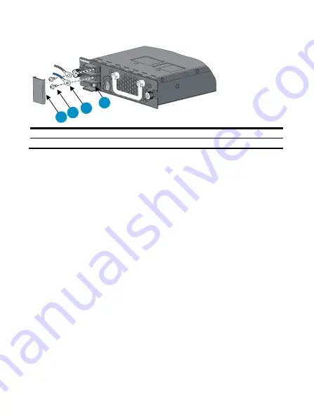
Figure 7


Connect a DC power cord 

+

1 2

3

4


(1) Protection cover 

(2) Screws 

(3) Wiring terminal 

(4) Grounding point 


© Copyright 2011 Hewlett-Packard Development Company, L.P. 
The information in this document is subject to change without notice. 
BOM: 3101A0BR 
Part number: 5998-1734 
Version: APW100 
 

Summary of Contents for A7502

Page 1: ... functions Support input under voltage protection output over voltage protection short circuit protection and overheat protection 1 1 redundancy support Support dual power grid 1 1 redundancy and current sharing using power supplies of the same model Hot swap support Support hot swap while the device is in operation CAUTION For a device that supports both AC and DC inputs you can choose either of ...

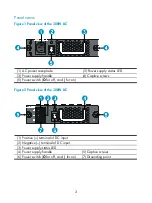
Page 2: ...ED 3 Power supply handle 4 Captive screws 5 Power switch O for off and for on Figure 2 Panel view of the 300W DC 1 Positive terminal of DC input 2 Negative terminal of DC input 3 Power supply status LED 4 Power supply handle 5 Captive screws 6 Power switch O for off and for on 7 Grounding point ...

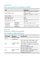
Page 3: ...re 40 C to 70 C 40 F to 158 F Status LED The 300W AC or 300W DC has one status LED Table 3 300W AC and 300W DC LED description Color status Description Possible causes Green The power supply is operational Power alarm input under voltage output short circuit output over current output over voltage or overheat occurred to the power supply and the power supply took a self protection action Red The p...

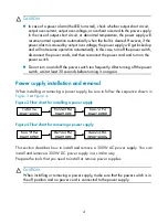
Page 4: ...on the power switch Do not turn on and off the power switch too frequently After turning off the power switch wait at least 30 seconds before turning it on again Power supply installation and removal When installing or removing a power supply be sure to follow the sequence shown in Figure 3 or Figure 4 Figure 3 Flow chart for installing a power supply Figure 4 Flow chart for removing a power suppl...

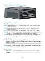
Page 5: ...ly with the right side up Grasp the handle of the module with one hand and support the module bottom with the other Step5 Gently push the power supply along the guide rails into the slot until it has firm contact with the backplane CAUTION To prevent damage to the power supply and the connection terminals on the backplane be sure to pull out the power supply first in case of any misalignment and t...

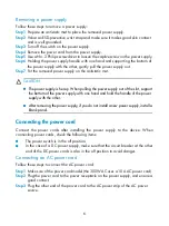
Page 6: ...f the slot support the bottom of the power supply with one hand and hold the handle of the power supply with the other After removing the power supply if you do not install a new power supply install a blank panel Connecting the power cord Connect the power cords after installing the power supply to the device When connecting power cords check the following items The power switch is in the off pos...

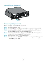
Page 7: ...ls Step3 Connect the end of the blue DC power cord marked with to the negative terminal on the power supply and fasten the screw Step4 Connect the end of the black DC power cord marked with to the positive terminals on the power supply and fasten the screw Step5 Put the protection cover on the wiring terminals Step6 Connect the other ends of the DC power cords to the wiring terminals that provide ...

Page 8: ... 4 1 Protection cover 2 Screws 3 Wiring terminal 4 Grounding point Copyright 201 1 Hewlett Packard Development Company L P The information in this document is subject to change without notice BOM 3101A0BR Part number 5998 1734 Version APW100 ...

Reviews: