
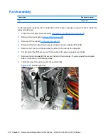


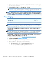


Fan Assembly
Description
Spare part number
Fan
656834-001
The fan assembly is attached to the inside floor of the chassis using two screws. The fan is inside of a
removal metal cage.
1.
Prepare the computer for disassembly (
Preparation for Disassembly on page 79
).
2.
Remove the access panel (
Access Panel on page 80
).
3.
Remove the front bezel (
Front Bezel on page 82
).
4.
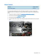
Disconnect the fan cable from the system board connector labeled SYS_FAN.
5.
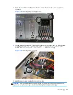
Remove the Torx screw that secures the left side of the fan to the computer.
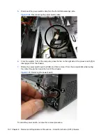
6.
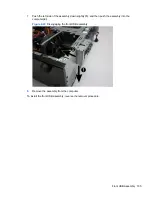
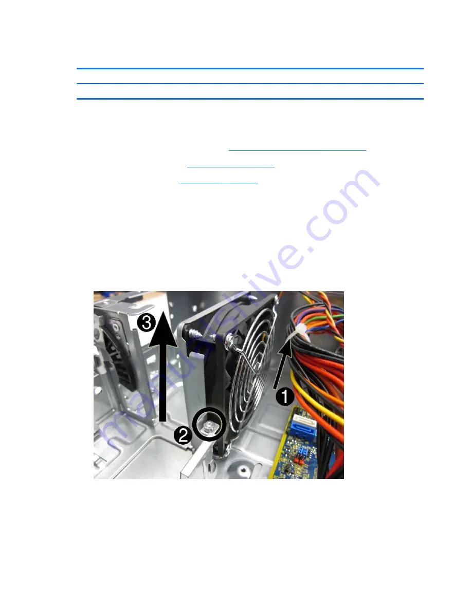
Cut the plastic tie
(1)
that secures the fan cable to the power supply power cables.
7.
Remove the two screws
(2)
that secure the fan to the computer. The screw near the computer
side is not shown in the following image.
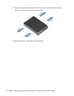
8.
Lift the fan assembly up and out of the computer
(3)
.
Figure 8-30
Removing the fan
106 Chapter 8 Removal and Replacement Procedures – Small Form Factor (SFF) Chassis
Summary of Contents for A7L26UT#ABA
Page 4: ...iv About This Book ...
Page 10: ...x ...