
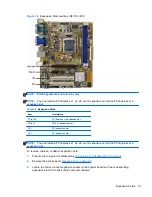


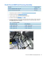


Figure 7-18
Front I/O connectors — HP Pro 3405 models
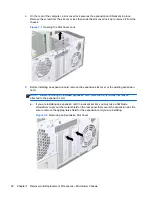
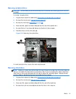
6.
Push in on the lever to the left of the assembly.
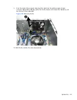
Figure 7-19
Front I/O connectors
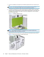
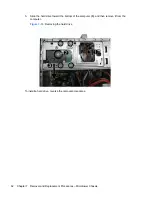
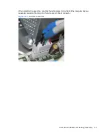
7.
Pull the assembly outward away from the front of the chassis while guiding the cables through
the hole in the chassis.
To install the housing assembly, reverse the removal procedures.
64
Chapter 7 Removal and Replacement Procedures – Microtower Chassis
Summary of Contents for A7L26UT#ABA
Page 4: ...iv About This Book ...
Page 10: ...x ...


