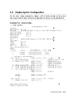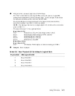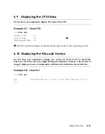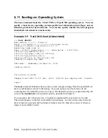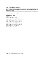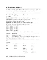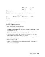
This part of the command output shows the PCI buses.
The “Slot” column lists the slots (logical IDs) seen by the system. Logical IDs
identify both installed PCI cards and onboard chips. In this example, the list shows
the onboard controllers and the Acer Labs M1543C IDE.
The logical IDs do not correspond directly to the physical slots into which the
devices are installed. See Table 5–4 for more details.
NOTE:
The naming of devices (for example,dqa0.0.0.13.0) follows the conventions
given in Table 5–5.
The slots in Example 5–2 are explained below.
Hose 0, Bus 0, PCI
Slot 7
Onboard Acer chip. Provides bridge to Bus 1 (ISA)
Slot 8
Onboard dual channel Adaptec SCSI controller
Slot 9
Onboard Ethernet controller
Slot 10
Onboard Ethernet controller
Slot 13
Onboard Acer chip IDE
Hose 0, Bus 1 (ISA)
Hose 2, Bus 0, PCI
Slot 7
ATI Radeon 7500 Graphics Accelerator running at 66 MHz
Jumpers
. State of jumpers
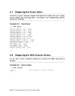
Table 5–4 How Physical I/O Slots Map to Logical Slots
Physical Slot SRM Logical Slot ID
1
Hose 2 Slot ID 7
2
Hose 2 Slot ID 8
3
Hose 2 Slot ID 9
4
Hose 2 Slot ID 10
Using Firmware
5-11

