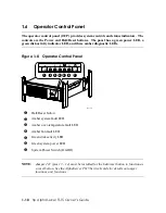
background image

1.9


Storage Cage Options 

The 

AlphaServer

 TS15 system comes with either an internal storage cage or a front 

access storage cage.  
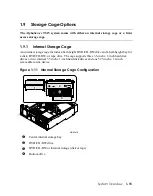
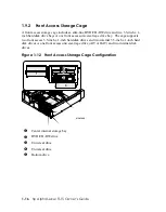
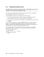
1.9.1


Internal Storage Cage 

An internal storage cage includes a half-height DVD/CD-RW drive and a half-height bay for 
a disk, DVD/CD-RW, or tape drive. The cage supports three 3.5-inch x 1-inch hard disk 
drives 

or

 two internal 3.5 inch x 1-inch hard disk drives and one 5.25-inch x 1.6-inch 

removable media device.  

Figure 1–11   Internal Storage Cage Configuration 

1

2

3

4

1

2

3

4

MR0591B


X


Center internal storage bay 

Y


DVD/CD-RW drive 

Z


DVD/CD-RW or internal storage (disk or tape) 

[


Bottom drive 


System Overview    

1-15


Summary of Contents for AlphaServer TS15

Page 1: ...s Guide Order Number EK TS150 OG A01 This manual is intended for system managers qualified self maintenance customers and others who need to perform system management tasks on AlphaServer TS15 systems Hewlett Packard Company ...

Page 2: ... A devices are those that may reasonably be expected to be installed in a business or commercial environment Class B devices are those that may reasonably be expected to be installed in a residential environment i e personal computers The FCC requires devices in both classes to bear a label indicating the interference potential of the device as well as additional operating instructions for the use...

Page 3: ... relocate the receiving antenna Increase the separation between the equipment and receiver Connect the equipment into an outlet on a circuit different from that to which the receiver is connected Consult the dealer or an experienced radio or television technician for help Declaration of Conformity for products marked with the FCC logo United States only This device complies with Part 15 of the FCC...

Page 4: ...g two conditions 1 this device may not cause harmful interference and 2 this device must accept any interference received including interference that may cause undesired operation Canadian Notice Avis Canadien Class A Equipment This Class A digital apparatus meets all requirements of the Canadian Interference Causing Equipment Regulations Cet appareil numérique de la classe A respecte toutes les e...

Page 5: ... R TTE Directive 1999 5 EC Compliance with these directives implies conformity to the following European Norms in parentheses are the equivalent international standards and regulations EN55022 CISPR 22 Electromagnetic Interference EN55024 IEC61000 4 2 3 4 5 6 8 11 Electromagnetic Immunity EN61000 3 2 IEC61000 3 2 Power Line Harmonics EN61000 3 3 IEC61000 3 3 Power Line Flicker EN60950 IEC60950 Pro...

Page 6: ......

Page 7: ...nal Storage Cage 1 16 1 9 2 Front Access Storage Cage 1 17 1 10 Console Terminal 1 18 1 11 Ground and Power Connections 1 20 1 12 System Access Lock 1 21 Chapter 2 Operating the System 2 1 Powering Up the System 2 2 2 2 Power Up Displays 2 3 2 2 1 SROM Power Up Display 2 4 2 2 2 SRM Console Power Up Display 2 5 2 3 SRM Console 2 7 2 3 1 Selecting the Display Device 2 8 2 4 Displaying the Hardware ...

Page 8: ... 3 1 6 ex _protocols 3 11 3 2 Booting Tru64 UNIX 3 12 3 2 1 Booting Tru64 UNIX over the Network 3 14 3 2 2 Setting Up the Watchdog Timer 3 16 3 3 Starting a Tru64 UNIX Installation 3 17 3 4 Booting OpenVMS 3 19 3 5 Booting OpenVMS from the InfoServer 3 21 3 6 Starting an OpenVMS Installation 3 23 Chapter 4 Installing and Configuring Options 4 1 Preparing to Install Options 4 2 4 2 Removing and Rep...

Page 9: ... SRM Command Summary 5 4 5 3 Getting Help 5 8 5 4 Displaying the Configuration 5 9 5 5 Displaying the Bootable Devices 5 12 5 6 Displaying the Memory Configuration 5 13 5 7 Displaying the Power Status 5 14 5 8 Displaying the SRM Console Version 5 14 5 9 Displaying the CPU Status 5 15 5 10 Displaying the PALcode Version 5 15 5 11 Booting an Operating System 5 16 5 12 Testing the System 5 18 5 13 St...

Page 10: ...6 11 6 5 Entering the RMC 6 12 6 6 Using the Command Line Interface 6 14 6 6 1 Displaying the System Status 6 15 6 6 2 Displaying the System Environment 6 19 6 6 3 Using Power On and Off Reset and Halt Functions 6 20 6 7 Configuring Remote Dial In 6 22 6 8 Configuring Dial Out Alert 6 26 6 9 RMC Firmware Update and Recovery 6 30 6 10 Resetting the RMC to Factory Defaults 6 33 6 11 RMC Command Refe...

Page 11: ... 2 10 Example 2 5 Show Config 2 11 Example 2 6 Show Device 2 14 Example 2 7 Show Memory 2 16 Example 2 8 Set Password 2 19 Example 2 9 Set Secure 2 20 Example 2 10 Login 2 21 Example 2 11 Clear Password 2 23 Example 2 12 Updating the Firmware 2 25 Example 3 1 Booting Tru64 UNIX from a Local SCSI Disk 3 12 Example 3 2 RIS Boot 3 14 Example 3 3 Text Based Installation Display 3 17 Example 3 4 Bootin...

Page 12: ...lity 6 31 Example 7 1 Memory Sizing 7 11 Example 7 2 Running LFU 7 16 Figures Figure 1 1 AlphaServer TS15 Systems Installed in NEBS Cabinet 1 2 Figure 1 2 Rackmount Details for AlphaServer TS15 System 1 3 Figure 1 3 Views of Optional Storage Cages 1 4 Figure 1 4 Top View 1 6 Figure 1 5 Rear Ports and Slots 1 8 Figure 1 6 Ethernet Network Connection 1 9 Figure 1 7 Network LED Indicators 1 10 Figure...

Page 13: ...Figure 4 20 Shared SCSI Operation Jumper 4 35 Figure 4 21 External SCSI Connector 4 36 Figure 4 22 Loadable Firmware Update Utility 4 37 Figure 6 1 Data Flow in Through Mode 6 4 Figure 6 2 Data Flow in Bypass Mode 6 6 Figure 6 3 Setup for RMC with VT Terminal 6 9 Figure 6 4 Setup for RMC with VGA Monitor 6 10 Figure 6 5 RMC Jumpers Default Positions 6 35 Figure 7 1 LED Patterns During Power Up 7 2...

Page 14: ... 7 4 Troubleshooting Power Problems 7 5 Table 7 5 Troubleshooting Console Reported Failures 7 6 Table 7 6 Troubleshooting Boot Problems 7 7 Table 7 7 Operating System Reported Failures 7 10 Table 7 8 Troubleshooting Memory Problems 7 11 Table A 1 Physical Characteristics AlphaServer TS15 A 2 Table A 2 NEBS Seismic Earthquake Cabinets A 2 Table A 3 Environmental Characteristics All System Variants ...

Page 15: ...e contains descriptions procedures and syntax definitions This owner s guide has seven chapters and one appendix Chapter 1 System Overview gives an overview of the system and describes the components Chapter 2 Operation gives basic operating instructions on powering up and configuring the machine setting console security and updating firmware Chapter 3 Booting and Installing an Operating System de...

Page 16: ...n that may be of special importance CAUTION A caution contains information essential to avoid damage to the equipment WARNING A warning contains information essential to protect the safety of personnel n Circled numbers provide a link between figures or examples and text Italic type Italic type emphasizes important information indicates variables and indicates complete titles of manuals Bold text ...

Page 17: ...stem including System Enclosure Configurations Common Components Front View Top View Rear Ports and Slots Network Connection Operator Control Panel System Motherboard PCI Slots Storage Cage Options Console Terminal Power Connection System Access Lock System Overview 1 1 ...

Page 18: ...p Al ph aS erve r TS 15 Cert ified Exce llenc e Certifi ed Excelle nce and Design is a certific ation mark of Telcor dia Certifi cation No 030005 NEBS Level 3 TM hp Al ph aS erve r TS 15 Cert ified Exce llenc e Certifi ed Excelle nce and Design is a certific ation mark of Telcor dia Certifi cation No 030005 NEBS Level 3 TM hp Al ph aS erve r TS 15 Cert ified Exce llenc e Certifi ed Excelle nce and...

Page 19: ...dia Certification No 030005 NEBS Level 3 TM CAUTION Disconnect all power cables before servicing to avoid an energy hazard ATTENTION D sconnectez tous les cables d alimentation avant chaque entretien afin d eviter tout accident lectrique ACHTUNG Ziehen Sie zur Vermeidung von Stromstš en vor der Wartung alle Netzkabel heraus PRECAUCIîN Desconecte todos los cables de alimentaci n antes de dar manten...

Page 20: ...storage cage o the front access storage cage p and the operator control panel q Figure 1 3 Views of Optional Storage Cages MR0650 1 1 3 2 4 4 4 hp AlphaServer TS15 Certified Excellence Certified Excellen ce and Design is a certifica tion mark of Telcordia Certifica tion No 030005 NEBS Level 3 TM 1 4 hp AlphaServer TS15 Owner s Guide ...

Page 21: ...controller with one port for internal storage and one port for external storage Choice of storage cage subsystems Internal Storage Cage with a SCSI storage capacity Front Access Storage Cage with a SCSI storage capacity Center internal storage bay internal SCSI drive Two serial ports COM1 port with both an RMC port with modem control and a full duplex asynchronous communications port COM2 port wit...

Page 22: ...View The following figure identifies most of the system components that can be seen after removing the cover Figure 1 4 Top View 1 2 3 4 9 7 6 5 11 12 13 14 14 8 10 MR0649 1 6 hp AlphaServer TS15 Owner s Guide ...

Page 23: ...VD CD RW drive Z Internal disk drive Power supply PCI riser I O devices CPU System motherboard _ Memory Speaker hidden a Center internal storage bay Cover Side wall Flip down door and front bezel EMI shielding System Overview 1 7 ...

Page 24: ...and data connections Figure 1 5 Rear Ports and Slots A 1 2 B MR0622 8 9 3 5 6 7 2 4 1 A B 1 2 X Serial port COM1 Y Serial port COM2 Z Mouse connector Keyboard connector SCSI port Ethernet port B Ethernet port A _ Dual power inputs A and B PCI option slots four available 1 8 hp AlphaServer TS15 Owner s Guide ...

Page 25: ... cable X to either Ethernet connector A Y or connector B Z Figure 1 6 Ethernet Network Connection A B MR0648 1 2 3 The following figure identifies the LED indicators to the left of each Ethernet connector Figure 1 7 Network LED Indicators A B 1 2 MR0529 X LED Speed Activity indicates activity through the connection Y LED Link indicator network connection exists when this LED is lit System Overview...

Page 26: ...e Certified Excellence and Design is a certification mark of Telcordia Certification No 030005 NEBS Level 3 TM MR0621 1 2 3 4 5 6 7 X Halt Reset button Y Amber system fault LED Z Amber over temperature fault LED Amber fan fault LED Green disk activity LED Green system power LED System Power Switch On Off NOTE Jumper J22 pins 13 14 must be installed for the halt reset button to function as a reset ...

Page 27: ...n RMC see Chapter 6 RMC Command Function Power on Turns on power Emulates pressing the Power button to the On position Power off Turns off power Emulates pressing the Power button to the Off position Halt Halts the system Halt in Halts the system and causes the halt to remain asserted Halt out Releases a halt created with halt in Reset Resets the system System Overview 1 11 ...

Page 28: ...1 7 System Motherboard This is the main logic board for the system and is fastened to the base of the enclosure Figure 1 9 System Motherboard 1 12 hp AlphaServer TS15 Owner s Guide ...

Page 29: ...nstructions during each CPU clock cycle and a peak instruction execution rate of four times the CPU clock frequency 1 7 2 Memory DIMMS The AlphaServer TS15 system supports up to two pairs of 200 pin synchronous dual inline memory modules DIMMs Supported DIMM sizes are 256 MB 512 MB and 1 GB allowing memory to be configured from 512 MB to 4096 MB 1 7 3 PCI Busses The AlphaServer TS15 system support...

Page 30: ...X Slot 1 66 33 MHz 3 3v use this slot first Y Slot 2 66 33 MHz 3 3v use this slot second Z Slot 3 33 MHz 3 3v use this slot third Slot 4 33 MHz 3 3v use this slot fourth r LED connected to 5 VAUX Table 1 1 How Physical I O Slots Map to Logical Slots Port Hose Physical Slot SRM Logical Slot A 2 1 7 2 8 3 9 4 10 1 14 hp AlphaServer TS15 Owner s Guide ...

Page 31: ...e and a half height bay for a disk DVD CD RW or tape drive The cage supports three 3 5 inch x 1 inch hard disk drives or two internal 3 5 inch x 1 inch hard disk drives and one 5 25 inch x 1 6 inch removable media device Figure 1 11 Internal Storage Cage Configuration 1 2 3 4 1 2 3 4 MR0591B X Center internal storage bay Y DVD CD RW drive Z DVD CD RW or internal storage disk or tape Bottom drive S...

Page 32: ...orts two front access 3 5 inch x 1 inch hard disk drives and two internal 3 5 inch x 1 inch hard disk drives or one front access universal tape drive AIT or DAT and two internal disk drives Figure 1 12 Front Access Storage Cage Configuration MR0590B 1 2 3 4 5 1 2 3 4 5 X Center internal storage bay Y DVD CD RW drive Z Universal drive Universal drive Bottom drive 1 16 hp AlphaServer TS15 Owner s Gu...

Page 33: ...serial character cell terminal connected to the COM1 port or a VGA monitor connected to a video card VGA adapter The following figures identify the proper connections Figure 1 13 Console Terminal Connected to COM1 Port B 1 2 A MR0646 System Overview 1 17 ...

Page 34: ...Figure 1 14 VGA Monitor Connected to Optional Video Card B 1 2 A MR0647 1 18 hp AlphaServer TS15 Owner s Guide ...

Page 35: ...pply is designed for dual redundant inputs and both power cables must be installed A ground cable connects the enclosure to the rack s vertical rail Figure 1 15 Ground and Power Connections A B A 1 2 B 3 4 5 1 MR0568 A B 1 3 2 System Overview 1 19 ...

Page 36: ... ground cable p fastens to the rack with a two 10 32 x 0 625 inch screws The power cables q r plug into the power supply at the rear of the enclosure and fasten with captive screws 1 12 System Access Lock The system enclosure has a key lock at the rear Due to the configuration of the enclosure this lock is not functional and can be ignored 1 20 hp AlphaServer TS15 Owner s Guide ...

Page 37: ...uctions for basic system operation The following topics are covered Powering up the system Power up displays SRM console Displaying the hardware configuration Setting SRM environment variables Setting console security Updating firmware Operating the System 2 1 ...

Page 38: ...t chaque entretien afin d eviter tout accident lectrique ACHTUNG Ziehen Sie zur Vermeidung von Stromstš en vor der Wartung alle Netzkabel heraus PRECAUCIîN Desconecte todos los cables de alimentaci n antes de dar mantenimiento para evitar que ocurran da os con la alimentaci n 36 50660 01 A01 MR0621 1 2 3 4 5 6 7 X Halt Reset button Y Amber system fault LED Z Amber over temperature fault LED Amber ...

Page 39: ...the kind of terminal that is connected as the console terminal either VT or VGA If the SRM console environment variable is set to serial the entire power up display consisting of the SROM and SRM power up messages is displayed on the VT terminal screen If console is set to graphics SROM messages are not displayed and the SRM messages are delayed until VGA initialization has completed If the COM1_m...

Page 40: ...00 MHz System Bus Speed 0125 MHz SROM program starting Bcache data tests in progress Bcache address test in progress CPU parity and ECC detection in progress Bcache ECC data tests in progress Bcache TAG lines tests in progress Memory sizing in progress Memory configuration in progress Testing AAR0 Memory data test in progress Memory address test in progress Memory pattern test in progress Memory i...

Page 41: ...de V1 96 40 Tru64 UNIX PALcode V1 90 31 starting console on CPU 0 initialized idle PCB initializing semaphores initializing heap initial heap 240c0 memory low limit 218000 heap 240c0 17fc0 initializing driver structures initializing idle process PID initializing file system initializing timer data structures lowering IPL CPU 0 speed is 1000 MHz create dead_eater create poll create timer create pow...

Page 42: ...he console environment variable If console is set to graphics the display from this point on is saved in a memory buffer and displayed on the VGA monitor after the PCI buses are sized and the VGA device is initialized The memory size is determined and memory is tested Memory testing is based on the memory_test environment variable none partial full The I O subsystem is probed and I O devices are r...

Page 43: ...y on the system board The SRM console firmware is described in detail in Chapter 5 Firmware The following sections cover functions you can perform from the SRM console Example 2 3 SRM Console Example set bootdef_dev dkb0 dka0 In this example the operator enters the SRM set command and specifies the devices from which to boot the operating system At power up the system will try to boot from SCSI de...

Page 44: ... port If you use a VGA monitor as the console terminal set the console environment variable to graphics You can verify the display device with the SRM show console command and change the display device with the SRM set console command If you change the display device setting you must reset the system with the Reset button if configured to reset RMC reset command SRM init command to put the new set...

Page 45: ... the system configuration show boot Displays the boot environment variables show config Displays the logical configuration of interconnects and buses on the system and the devices found on them show device Displays the bootable devices and controllers in the system show fru Displays the physical configuration of FRUs field replaceable units See Chapter 5 for information on this command show memory...

Page 46: ...e name used for the primary bootstrap when no file name is specified by the boot command boot_osflags Boot flags here the Tru64 UNIX a autoboot flag boot_reset Action taken in response to an error halt or to a boot command OFF the default indicates a warm boot no full reset is performed bootdef_dev Device or device list from which booting is to be attempted when no path is specified on the command...

Page 47: ...C Runtime V1 1 0 RMC Booter V1 1 0 Processors CPU 0 Alpha EV68CB pass 4 0 1000 MHz 2MB Bcache Core Logic Cchip Rev 18 Dchip Rev 17 PPchip 0 Rev 17 TIG Rev 1 11 Acer Chip Revision A1 E Memory Array Size Base Address Intlv Mode 0 1024Mb 0000000000000000 2 Way 2 1024Mb 0000000040000000 2 Way 2048 MB of System Memory Slot Option Hose 0 Bus 0 PCI 33 MHz 7 Acer Labs M1543C Bridge to Bus 1 ISA 8 0 Adapte...

Page 48: ...at form the interconnect on the motherboard Memory Memory arrays and memory size This part of the command output shows the PCI buses The Slot column lists the slots logical IDs seen by the system Logical IDs identify both installed PCI cards and onboard chips The logical IDs do not correspond directly to the physical slots into which the devices are installed See Table 2 1 for the correspondence b...

Page 49: ...Slot ID 9 4 Hose 2 Slot ID 10 2 4 3 Displaying the Bootable Devices Use the show device command to display the devices from which the operating system can be booted Example 2 6 Show Device show device dka0 0 0 8 0 DKA0 COMPAQ BF03665A32 3B01 dka100 1 0 8 0 DKA100 COMPAQ BF03665A32 3B01 dqa0 0 0 13 0 DQA0 DW 224E A 1J dva0 0 0 1000 0 DVA0 eia0 0 0 9 0 EIA0 00 02 A5 20 C0 39 eib0 0 0 10 0 EIB0 00 02...

Page 50: ... tape eg Ethernet port pu DSSI port ei Ethernet port pz KZPCC CE RAID controller a Storage adapter ID One letter designator of storage adapter a b c 0 Device unit number Unique number MSCP unit number SCSI unit numbers are forced to 100 X node ID 0 Bus node number Bus node ID 0 Channel number Used for multi channel devices 13 Logical slot number IDE that is onboard 0 Hose number 0 PCI 0 2 PCI 2 2 ...

Page 51: ...1024 MB of System Memory Explanation The show memory display corresponds to the memory array configuration described in Chapter 4 The display does not indicate the number of DIMMs or the DIMM size The output of the show memory command also provides the memory interleaving status of the system Use the show fru command to display the DIMMs in the system and their location See Chapter 5 Operating the...

Page 52: ... variables enter the show command For example to display the default boot device use show bootdef_dev To reset an environment variable use the set envar command where the name of the environment variable is substituted for envar For example to set the default boot device to dkb0 use set bootdef_dev dkb0 To turn off console security for the current console session use the login command The environm...

Page 53: ... boots the operating system using the environment variables stored in NVRAM boot_file bootdef_dev boot_osflags The console security commands are as follows set password set secure These commands put the console into secure mode clear password Exits secure mode login Turns off console security for the current session Once you enter the login command in secure mode you can enter any SRM command as u...

Page 54: ... to set the password only if the system is going to operate in secure mode The syntax is set password Setting a password If a password has not been set and the set password command is issued the console prompts for a password and verification The password and verification are not echoed Changing a password If a password has been set and the set password command is issued the console prompts for th...

Page 55: ... password Once you set a password and enter the set secure command secure mode is in effect immediately and only the continue boot using the stored parameters and login commands can be performed The syntax is set secure The console is put into secure mode and then the operator attempts to boot the operating system with command line parameters A message is displayed indicating that boot parameters ...

Page 56: ...set Example 2 10 Login login Secure not set Please set the password set password Please enter the password Please enter the password again login Please enter the password show boot Explanation The login command is entered but the system is not in secure mode A password must be set A password is set The login command is entered After the password is entered console security is turned off for the cu...

Page 57: ...console commands can be performed during the current console session If You Forget the Password If you forget the current password use the login command in conjunction with an RMC halt in out to clear the password as follows 1 Enter the login command login 2 When prompted for the password enter the RMC and issue the halt in command press the Return Enter key 3 At the SRM prompt enter the clear pas...

Page 58: ...ully cleared Explanation The wrong password is entered The system remains in secure mode The password is successfully cleared The clear password command is used to exit secure mode and return to user mode To use clear password you must know the current password Once you clear the password the console is no longer secure To clear the password without knowing the current password you must use the lo...

Page 59: ...ate files from the Internet http ftp digital com pub DEC Alpha firmware 2 7 1 Using the Loadable Firmware Update Utility The system firmware is updated from a Loadable Firmware Update Utility LFU When you boot the medium containing the update image the LFU banner and command descriptions are displayed Enter commands at the UPD prompt Before updating the firmware enter the list command to list the ...

Page 60: ...lls this function table UPD list Device Current Revision Filename Update Revision SRM V6 3 1 srm_fw V6 3 1 srom V1 3 F srom_fw V1 3 F rt V0 5 6 rt_fw V0 5 9 rt RMC Runtime cipca_fw A420 dfxaa_fw 3 20 fca_2354_fw CS3 81A4 kgpsa_8k_fw DS3 81A4 kzpcc_smor 1 12 kzpcc_fw CQ16 kzpsa_fw A12 UPD update srm Confirm update on srm Y N y WARNING updates may take several minutes to complete for each device DO ...

Page 61: ...name and update revision Update Replaces current firmware with loadable data image Verify Compares loadable and hardware images or Help Scrolls this function table UPD exit Do you want to do a manual update y n y Loadable Firmware Update Utility Function Description Display Displays the system s configuration table Exit Done exit LFU reset List Lists the device revision firmware name and update re...

Page 62: ...pdate the system firmware from CD ROM 1 At the SRM console prompt enter the show device command to determine the drive name of the CD ROM drive 2 Load the Alpha Systems Firmware Update CD into the drive 3 Boot the system from the CD using the drive name determined in step 1 for example dqa0 boot dqa0 4 Enter the update command at the UPD prompt 5 When the update is complete exit from the Firmware ...

Page 63: ...update exe system_disk sys0 sysexe NOTE Insert the name of your system disk in place of system_disk for example dka100 4 Shut down the operating system to get to the SRM console prompt 5 Boot the update utility from the SRM console as follows boot dka100 flags 0 a0 NOTE Replace dka100 with the name of the system disk if different 6 After some messages are displayed you will be prompted for the boo...

Page 64: ...d at the UPD prompt Updating Firmware Using MOP 1 Download the firmware update image from the Firmware Updates Web site 2 Copy the downloaded file to an OpenVMS based network server for MOP booting on the system For details on configuring the MOP server refer to OpenVMS documentation or the system s Firmware Release Notes document 3 To ensure that the downloaded file is in a proper VMS fixed recor...

Page 65: ...ooting or starting an installation The following topics are included Setting Boot Options Booting Tru64 UNIX Starting a Tru64 UNIX Installation Booting OpenVMS Booting OpenVMS from the InfoServer Starting an OpenVMS Installation NOTE Your system may have been delivered to you with factory installed software FIS that is with a version of the operating system already installed If so refer to the FIS...

Page 66: ...e bootdef_dev Device or device list from which booting is to be attempted when no path is specified on the command line boot_file Specifies a default file name to be used for booting when no file name is specified by the boot command boot_osflags Defines parameters boot flags used by the operating system to determine some aspects of a system bootstrap eg 0_inet_init ei 0_inet_init ew 0_inet_init D...

Page 67: ... the system boots from whatever device it booted from before the shutdown reset or failure NOTE After you set the auto_action environment variable it is recommended that you set the boot device and operating system flags as well using the set bootdef_dev and set boot_osflags commands The syntax is set auto_action value The options for value are halt The system remains in console mode after power u...

Page 68: ...t show auto_action auto_action restart show bootdef_dev bootdef_dev dka0 boot Login to UNIX and shutdown reboot shutdown r now console will boot from dka0 In the following example auto_action is set to restart but Tru64 UNIX is booted from a device other than the device set with bootdef_dev When Tru64 UNIX is shut down and rebooted the system reboots from the specified device boot dka100 Log in to...

Page 69: ... of all devices in the system The syntax is set bootdef_dev boot_device boot_device The name of the device on which the system software has been loaded To specify more than one device separate the names with commas Example In this example two boot devices are specified The system will try booting from dkb0 and if unsuccessful will boot from dka0 set bootdef_dev dkb0 dka0 NOTE When you set the boot...

Page 70: ...name to be used for booting when no file name is specified by the boot command The factory default value is null The syntax is set boot_file filename Example In this example the system is set to boot using the file vmunix set boot_file vmunix 3 6 hp AlphaServer TS15 Owner s Guide ...

Page 71: ...4 UNIX Systems Tru64 UNIX systems take a single ASCII character as the flags_value argument a Load operating system software from the specified boot device autoboot Boot to multi user mode i Prompt for the name of a file to load and other options boot interactively Boot to single user mode s Stop in single user mode Boots vmunix to single user mode and stops at the root prompt D Full dump implies ...

Page 72: ...ple the flag value 10080 executes both the 80 and 10000 flag settings See Table 3 1 Table 3 1 OpenVMS Boot Flag Settings Flags_Value Bit Number Meaning 1 0 Bootstrap conversationally enables you to modify SYSGEN parameters in SYSBOOT 2 1 Map XDELTA to a running system 4 2 Stop at initial system breakpoint 8 3 Perform diagnostic bootstrap 10 4 Stop at the bootstrap breakpoints 20 5 Omit header from...

Page 73: ...from nvram or from a network server through the bootp protocol Legal values are nvram and bootp The default value is bootp Set this environment variable if you are booting Tru64 UNIX from a RIS server To list the network devices on your system enter the show device command The Ethernet controllers start with the letters eg ei or ew for example ewa0 The third letter is the adapter ID for the specif...

Page 74: ...otocol_value The options for protocol_value are mop default Sets the network protocol to mop Maintenance Operations Protocol the setting typically used with the OpenVMS operating system bootp Sets the network protocol to bootp the setting typically used with the Tru64 UNIX operating system bootp mop When both are listed the system attempts to use the mop protocol first regardless of which is liste...

Page 75: ...fff0000 initializing machine state setting affinity to the primary CPU jumping to bootstrap code UNIX boot Wednesday October 16 2002 Loading vmunix Loading at 0xfffffc0000430000 Sizes text 5214016 data 852864 bss 1780768 Starting at 0xfffffc00004415e0 Alpha boot available memory from 0x44ec000 to 0x7ffee000 Compaq Tru64 UNIX V5 1B Rev 2650 Tue May 6 11 27 46 EST 2003 physical memory 2048 00 megaby...

Page 76: ...0 VGA 16 colors vga0 generic VGA driver Created FRU table binary error log packet kernel console ace0 dli configured NetRAIN configured Random number generator configured vm_swap_init swap is set to lazy over commitment mode INIT SINGLE USER MODE Explanation Perform the following tasks to boot a Tru64 UNIX system 1 Power up the system The system stops at the SRM console prompt 2 Set boot environme...

Page 77: ...ple appears after the example Example 3 2 RIS Boot show device X dka0 0 0 8 0 DKA0 COMPAQ BF03665A32 3B01 dka100 1 0 8 0 DKA100 COMPAQ BF03665A32 3B01 dqa0 0 0 13 0 DQA0 DW 224E A 1J dva0 0 0 1000 0 DVA0 eia0 0 0 9 0 EIA0 00 02 A5 20 C0 39 eib0 0 0 10 0 EIB0 00 02 A5 20 C0 3A pka0 7 0 8 0 PKA0 SCSI Bus ID 7 pkb0 7 0 108 0 PKB0 SCSI Bus ID 7 set ega0_protocols bootp Y set ega0_inet_init bootp Z boo...

Page 78: ...ting from ega0 If you are booting from another adapter enter that device name instead set ega0_protocols bootp set ega0_inet_init bootp The first set command Y enables the bootp network protocol for booting over the Ethernet controller The second set command Z sets the internal Internet database to initialize from the network server through the bootp protocol 5 Enter the boot command and command l...

Page 79: ...the operating system the watchdog timer functionality is turned off by default but is controlled by the titan system attribute called hbrick_watchdog_timer_enable This attribute can be set for the current session with the sysconfig command or longer term via the etc sysconfigtab file To turn it on dynamically via sysconfig enter the following command sysconfig r titan hbrick_watchdog_timer_enable ...

Page 80: ... installation Please wait Performing CDROM Installation Loading installation process and scanning system hardware Welcome to the Tru64 UNIX Installation Procedure This procedure installs Tru64 UNIX onto your system You will be asked a series of system configuration questions Until you answer all questions your system is not changed in any way During the question and answer session you can go back ...

Page 81: ...tallation with Worldwide Language Support 3 Exit Installation Enter your choice Explanation 1 Boot the operating system from the CD ROM drive connected to the system 2 Follow the Tru64 UNIX installation procedure that is displayed after the installation process is loaded If your system console is a VGA monitor the X Server is started and an Installation Setup window is displayed Click on the field...

Page 82: ...000 0 DVA0 eia0 0 0 9 0 EIA0 00 02 A5 20 C0 39 eib0 0 0 10 0 EIB0 00 02 A5 20 C0 3A pka0 7 0 8 0 PKA0 SCSI Bus ID 7 pkb0 7 0 108 0 PKB0 SCSI Bus ID 7 boot flags 0 0 dqa0 Y boot dqa0 0 0 7 1 flags 0 0 block 0 of dqa0 0 0 7 1 is a valid boot block reading 898 blocks from dqa0 0 0 7 1 bootstrap code read in base 200000 image_start 0 image_bytes 70400 initializing HWRPB at 2000 initializing page table...

Page 83: ...t variables if desired See Section 3 1 3 Install the boot medium For a network boot see Section 3 5 4 Enter the show device command X to determine the adapter ID and unit number of the drive for your device 5 Enter the boot command and command line parameters if you have not set the associated environment variables In the preceding example the boot command with the flags option Y causes the system...

Page 84: ...0 0 13 0 DQA0 DW 224E A 1J dva0 0 0 1000 0 DVA0 eia0 0 0 9 0 EIA0 00 02 A5 20 C0 39 eib0 0 0 10 0 EIB0 00 02 A5 20 C0 3A pka0 7 0 8 0 PKA0 SCSI Bus ID 7 pkb0 7 0 108 0 PKB0 SCSI Bus ID 7 boot flags 0 0 file apb_0731 eia0 Y boot eia0 0 0 9 0 file APB_0731 flags 0 0 Trying MOP boot Network load complete Host name CALSUN Host address aa 00 04 00 a4 4e bootstrap code read in base 200000 image_start 0 ...

Page 85: ... Insert the operating system CD ROM into the CD ROM drive connected to the InfoServer 3 Enter the show device command X to determine the unit number of the drive for your device 4 Enter the boot command and any command line parameters Y In the preceding example the device is EIA0 APB_0731 is the file name of the APB program used for the initial system load ISL boot program The InfoServer ISL progr...

Page 86: ...u can install or upgrade layered products that are included on the OpenVMS Alpha operating system CD ROM You can also execute DCL commands and procedures to perform standalone tasks such as backing up the system disk Please choose one of the following 1 Upgrade install or reconfigure OpenVMS Alpha Version V7 3 1 2 Display products and patches that this procedure can install 3 Install or upgrade la...

Page 87: ... understand the hazards of working within this equipment and take measures to minimize danger to themselves or others These measures include 1 Remove any jewelry that may conduct electricity 2 If accessing the system card cage power down the system and wait 2 minutes to allow components to cool 3 Wear an antistatic wrist strap when handling internal components WARNING To prevent injury and possibl...

Page 88: ... replace all other options and components Options Installable by the Customer Memory DIMMs PCI options Front access storage cage Internal storage cage Optional hard disks tape drive Before Opening the Enclosure or Installing Components 1 Shut down the operating system according to the instructions in the operating system documentation 2 Shut down peripheral devices 3 Press the Power button on the ...

Page 89: ...trol panel and attach your antistatic wrist strap 2 Go to the rear of the cabinet locate the back panel of the AlphaServer TS15 enclosure and disconnect both power connectors Also disconnect the ground cable and all other cables from the enclosure 3 As show in the next figure loosen the thumbscrews n to open the front door Remove the four screws o that fasten the front bezel p to the enclosure s f...

Page 90: ...enclosure from the rack and place it on a tabletop 3 As shown in Figure 4 3 remove the three M4 screws n on the hinged side p of the enclosure and fully loosen the three captive screws o on the other side 4 Rotate the enclosure so that the hinged edge is slightly overhanging the tabletop Lift up the captive screw side q of the cover and disengage the tabs from the slots on the hinged side Lift the...

Page 91: ...Figure 4 3 Removing the Top Cover A 2 1 4 5 3 MR0642 Installing and Configuring Options 4 5 ...

Page 92: ...and tighten the three captive screws o on the other side to 13 15 ft lb Reinstalling the Enclosure 1 Slide the enclosure into the rack Be sure to align the rear tabs q with the rack slides as shown in Figure 4 2 2 As shown in the same figure insert the four screws n that fasten the enclosure o to the rack 3 As show in Figure 4 1 install the front bezel by inserting the four screws o into the enclo...

Page 93: ...g the Center Internal Storage Bay MR0629 4 3 4 2 1 2 Removing the Center Internal Storage Bay 4 Shut down the system and remove the top cover as explained in Section 4 2 5 As shown in the preceding figure pull the two spring loaded pull pins o at the rear of the storage bay n and slide the unit toward the back of the enclosure 6 Lift the storage bay from the enclosure and turn it over Installing a...

Page 94: ...rage Bay 3 3 4 1 2 MR0532 Replacing the Disk in the Center Internal Storage Bay 1 Remove the four screws p from the bottom of the storage bay and slide the disk drive q out 9 Install the new disk drive and replace the bottom screws 10 Referring to preceding Figure 4 4 connect the data cable p and power cable q to the new disk drive n 11 Slide the storage bay forward into the enclosure 4 8 hp Alpha...

Page 95: ...control panel Boot the operating system 4 4 Status LEDs on Front Access Drives Storage drives in the optional front access storage cage provide three status LEDs that display activity power and drive fault The following figure shows the position and purpose of these LEDs Figure 4 6 LEDs on the Front Access Drive Front View MR0308B LED Status Green indicates activity Green indicates drive state Amb...

Page 96: ...he activity LED is off 2 To remove the drive press in the colored rubber button X to release the handle 3 Pull the handle Y forward to release the SCSI connection and then pull the drive from the cage If only one disk drive is installed a filler plate p fills the other drive slot 4 Insert the new disk drive into the cage with the front handle o fully opened With the drive resting on top of the rai...

Page 97: ...e Y to remove the drive from the cage A plastic filler p slides out with the tape drive 4 Snap the new plastic filler onto the new tape drive 5 Insert the new tape drive into the cage With the drive resting on top of the rail guides of the cage slide the drive in until it stops 6 Push the handle Y to make the backplane connection Verify that the locking tab n snaps into place Verification You must...

Page 98: ...t and the alternative to the internal storage cage You must remove this cage to access the bottom disk drive Refer to the following figure and procedure when removing this cage Figure 4 9 Accessing the Front Access Storage Cage MR0631 8 1 9 6 3 7 4 5 12 14 13 4 12 hp AlphaServer TS15 Owner s Guide ...

Page 99: ...ver to access the remaining cables 5 Remove the SCSI cable Z and power cable 6 Disconnect the fan cable from the motherboard All the cables are routed through the top slot area _ except the fan cable which is routed through the lower slot area The cage is now completely disconnected 7 Reverse the procedure steps 6 to 2 to install the storage cage 15 Replace the top cover and reassemble the system ...

Page 100: ... Cage The bottom disk drive provides optional storage Refer to the following figure and procedure when replacing a bottom drive Figure 4 10 Replacing Bottom Drive Front Access Storage Cage 1 2 1 MR0593A 4 14 hp AlphaServer TS15 Owner s Guide ...

Page 101: ...e 4 Slide the new drive into the cage and insert the four screws 5 Reinstall the front access storage cage as explained in Section 4 6 6 Replace the top cover and reassemble the system enclosure as explained in the end of Section 4 2 7 Turn on system power by pressing the power switch on the operator control panel Boot the operating system Verification Enter the SRM and use the init and show devic...

Page 102: ...the alternative to the front access storage cage You must remove this cage to access its internal storage devices Refer to the following figure and procedure when removing this cage Figure 4 11 Accessing the Internal Storage Cage MR0630 3 5 6 4 12 14 13 7 1 4 16 hp AlphaServer TS15 Owner s Guide ...

Page 103: ...a cable power cable from the DVD CD RW drive All the cables are routed through the top slot area 5 Remove the SCSI cable p and power cable 6 Reverse the procedure steps 5 to 2 to install the storage cage 7 Since this storage cage does not have a fan verify that the Feature_4 jumper is installed See Section 6 10 for details 8 Replace the top cover and reassemble the system enclosure as explained in...

Page 104: ...rage Cage The bottom disk drive provides optional storage Refer to the following figure and procedure when replacing a bottom drive Figure 4 12 Replacing Bottom Drive Internal Storage Cage 2 1 1 MR0592A 4 18 hp AlphaServer TS15 Owner s Guide ...

Page 105: ...age 4 Slide the new drive into the cage and insert the four screws 5 Reinstall the storage cage as explained in Section 4 8 6 Replace the top cover and reassemble the system enclosure as explained in the end of Section 4 2 7 Turn on system power by pressing the power switch on the operator control panel Boot the operating system Verification Enter the SRM and use the init and show device commands ...

Page 106: ...age Cage The middle drive provides optional storage Refer to the following figure and procedure when replacing a middle drive Figure 4 13 Replacing Middle Drive Internal Storage Cage 1 3 2 4 4 2 5 MR0594A 4 20 hp AlphaServer TS15 Owner s Guide ...

Page 107: ...Set the drive aside 5 Insert the new drive into the drive assembly and fasten the four bottom screws 6 Slide the drive assembly into the storage cage and fasten the four side screws 7 Reinstall the storage cage as explained in Section 4 8 8 Replace the top cover and reassemble the system enclosure as explained in the end of Section 4 2 9 Turn on system power by pressing the power switch on the ope...

Page 108: ...top drive is a half height DVD CR RW drive for use with optical media Refer to the following figure and procedure when replacing a DVD CD RW drive Figure 4 14 Replacing DVD CD RW Drive Internal Storage Cage PK0277A 1 1 2 4 22 hp AlphaServer TS15 Owner s Guide ...

Page 109: ... stock clips if they hang up on the drive 5 Before installing the new drive be sure all eight 8 EMC finger stock clips are in place 6 Slide the new drive into the storage cage and insert the four screws as shown 7 Reinstall the storage cage as explained in Section 4 8 8 Replace the top cover and reassemble the system enclosure as explained in the end of Section 4 2 9 Turn on system power by pressi...

Page 110: ...tacked DRAMs and to have interleaved memory all DIMMs in the system must be the same The addressed arrays are 0 and 2 4 12 2 Physical Layout on the System Motherboard Refer to Figure 1 9 for the DIMM slot layout on the system motherboard The memory slots are organized as follows J14 Array0 DIMM0 J15 Array2 DIMM2 J12 Array0 DIMM1 J13 Array2 DIMM3 4 12 3 Configuration Rules The following configurati...

Page 111: ...ce 1024MB 512MB 512MB 1536MB 256MB 512MB 256MB 512MB 1536MB 512MB 256MB 512MB 256MB 2048MB 512MB 512MB 512MB 512MB Recommended for performance 2048MB 1024MB 1024MB 2560MB 1024MB 256MB 1024MB 256MB 2560MB 256MB 1024MB 256MB 1024MB 3072MB 1024MB 512MB 1024MB 512MB 3072MB 512MB 1024MB 512MB 1024MB 4096MB 1024MB 1024MB 1024MB 1024MB Recommended for performance Installing and Configuring Options 4 25 ...

Page 112: ...IMM Figure 4 15 PCI Riser LED MR0502A 1 Installing a Memory DIMM To install a memory DIMMs follow these steps 1 To prepare to replace or add DIMMs see preceding section 4 1 2 Use Table 4 1 and the preceding Memory Configuration Rules to determine where sets of memory DIMMs should be installed 3 Shut down the system and remove the top cover as explained in Section 4 2 4 Remove the optional center i...

Page 113: ... the DIMM slot Verification 1 Turn on power to the system 2 At the SRM prompt issue the show memory command to display the amount of memory in each array and the total memory in the system Figure 4 17 Removing a DIMM 1 Release the clips X securing the appropriate DIMM Y 2 Slide out the DIMM as shown in the preceding figure Installing and Configuring Options 4 27 ...

Page 114: ...3 volt slots At the time of manufacture the PCI option modules are installed starting with slot 1 then 2 3 and 4 depending on the customer s configuration For consistency and ease of maintenance HP recommends that you install modules in the same sequence Some PCI options require drivers to be installed and configured These options come with a CD ROM Refer to the installation document that came wit...

Page 115: ...stand the hazards of working within this equipment and take measures to minimize danger to themselves or others WARNING To prevent fire use only modules with current limited outputs See National Electrical Code NFPA 70 or Safety of Information Technology Equipment Including Electrical Business Equipment EN 60 950 WARNING High current area Currents exceeding 240 VA can cause burns or eye injury Avo...

Page 116: ...ivers to be installed and configured These modules come with a CD ROM Refer to the installation document that came with the module and follow the manufacturer s instructions Figure 4 18 Installing a PCI Option Module 3 1 MR0633 1 2 4 4 30 hp AlphaServer TS15 Owner s Guide ...

Page 117: ...nclosure as explained at the end of Section 4 2 6 Turn on system power by pressing the power switch on the operator control panel Boot the operating system Verification 1 Turn on power to the system 2 At the prompt enter the SRM show config command Examine the PCI bus information in the display to make sure that the new option is listed 3 If you installed a bootable device enter the SRM show devic...

Page 118: ...nal graphics card is available as a PCI option The kit 3X PBXGG TA includes the graphics card a support bracket and hardware The card must be installed in PCI slot 1 Figure 4 19 Installing an ATI Radeon Graphics Card 4 32 hp AlphaServer TS15 Owner s Guide ...

Page 119: ...ight edge of the PCI riser and the Radeon card CAUTION Notice that the lower bracket q is loosely fastened to the support bracket by two screws r Be careful not to damage any components near the right edge of the Radeon card 6 Fasten the support bracket to the right edge of the PCI riser using the two screws s provided 7 Push up the lower bracket q and tighten the two screws r to secure the right ...

Page 120: ...the maximum number of devices supported on the SCSI controller to be used Each device on the bus must have a unique SCSI ID The entire SCSI bus length from terminator to terminator must not exceed the following limits Fast differential SCSI or Ultra SCSI HVD 25 meters Fast single ended SCSI 3 meters Ultra wide SCSI 1 5 meters Ultra 2 SCSI LVD 12 meters Ultra 3 SCSI 12 meters Ensure that the SCSI b...

Page 121: ...for that SCSI bus Additional setup is required including modifying parameters through the SCSI BIOS Refer to the appropriate Tru64 UNIX documentation for complete information on shared bus support and setup Note that when not operating on a shared bus J41 must removed and all SCSI BIOS parameters must be reset to their default values otherwise unpredictable system behavior may result Figure 4 20 S...

Page 122: ...Figure 4 21 External SCSI Connector A A B 1 2 B 1 MR0628 This figure shows the location of the external SCSI connector X 4 36 hp AlphaServer TS15 Owner s Guide ...

Page 123: ...pdate revision Lfu Restarts LFU Readme Lists important release information Update Replaces current firmware with loadable data image Verify Compares loadable and hardware images or Help Scrolls this function table UPD 4 16 1 Sources of Firmware Updates The system firmware resides in the flash ROM located on the system board The Alpha Systems Firmware Update Kit comes on a CD ROM which is updated q...

Page 124: ...a firmware readme html 1 Shut down the operating system 2 Turn the system power off and then on 3 At the SRM console prompt enter the show device command to determine the drive name of the CD ROM drive 4 Load the Alpha Systems Firmware Update CD into the drive 5 Boot the system from the CD using the drive name determined in step 1 for example dqa0 boot dqa0 6 At the UPD prompt enter the list comma...

Page 125: ... this chapter are SRM Console Overview SRM Command Summary Getting Help Displaying the Configuration Displaying the Bootable Devices Displaying the Memory Configuration Displaying the Power Status Displaying the SRM Console Version Displaying the CPU Status Displaying the PALcode Version Booting an Operating System Testing the System Updating Firmware Forcing a System Crash Dump Initializing the S...

Page 126: ...ike the UNIX more command For a full listing of available commands enter help more Console Prompt The SRM console prompt is some variant of three right angle brackets Change Prompt The following is an example of how to show and change the prompt display show prompt prompt set prompt system1 system1 system1 system1 Environment Variables SRM has environment variables a number of which are predefined...

Page 127: ...ure described in your operating system documentation You can also force entry to the SRM console if the auto_action environment variable is set to boot or reset To force entry press the halt reset button on the control panel Note Jumper J22 pins 13 14 on the system motherboard must not be inserted to force entry with the Halt button installed reset not installed halt Halt is the default mode CAUTI...

Page 128: ...sole line editor on a RAM script or on the user power up script nvram which is always invoked during the power up sequence halt Halts processor Same as stop help or man command Displays information about the specified console command init Resets the SRM console and reinitializes the hardware login Turns off secure mode enabling access to all SRM console commands during the current session more fil...

Page 129: ...cters to identify the keyword unambiguously Abbreviation of environment variables is allowed with the show command Options You can use command options to modify the environment after the command keyword or after any symbol or number in the command See individual command descriptions for examples Numbers Most numbers in console commands are in decimal notation No characters A command line with no c...

Page 130: ...rl C Terminates the process that is running Clears Ctrl S resumes output suspended by Ctrl O When entered as part of a command line deletes the current line Ctrl C has no effect as part of a binary data stream Left arrow Moves the cursor left one position Ctrl E Moves the cursor to the end of the line Ctrl F or right arrow Moves the cursor right one position Ctrl H Moves the cursor to the beginnin...

Page 131: ...mmand is useful for hardcopy terminals Ctrl S Suspends output to the console terminal until Ctrl Q is entered Cleared by Ctrl C Ctrl U Deletes the current line Wildcarding for commands such as show Double quotes enable you to denote a string for environment variable assignment Specifies that all text between it and the end of the line is a comment Control characters are not considered part of a co...

Page 132: ...e help or man command displays basic information about the use of console commands when the system is in console mode The syntax is help or man command command Command or topic for which help is requested The options are none Displays the complete list of commands for which you can receive help command_name Displays information about the console command argument_string such as sh Displays informat...

Page 133: ...9 Acer Chip Revision A1 E Memory Array Size Base Address Intlv Mode 0 1024Mb 0000000000000000 2 Way 2 1024Mb 0000000040000000 2 Way 2048 MB of System Memory Slot Option Hose 0 Bus 0 PCI 33 MHz 7 Acer Labs M1543C Bridge to Bus 1 ISA 8 0 Adaptec AIC 7899 pka0 7 0 8 0 SCSI Bus ID 7 dka0 0 0 8 0 COMPAQ BF03665A32 dka100 1 0 8 0 COMPAQ BF03665A32 8 1 Adaptec AIC 7899 pkb0 7 0 108 0 SCSI Bus ID 7 9 Inte...

Page 134: ...e following items explain the preceding example Firmware Version numbers of the SRM console PALcode serial ROM RMC runtime and RMC booter Processors Processors present processor version and clock speed and amount of backup cache Core logic Version numbers of the chips that form the interconnect on the system board Memory Memory arrays and memory size 5 10 hp AlphaServer TS15 Owner s Guide ...

Page 135: ...le dqa0 0 0 13 0 follows the conventions given in Table 5 5 The slots in Example 5 2 are explained below Hose 0 Bus 0 PCI Slot 7 Onboard Acer chip Provides bridge to Bus 1 ISA Slot 8 Onboard dual channel Adaptec SCSI controller Slot 9 Onboard Ethernet controller Slot 10 Onboard Ethernet controller Slot 13 Onboard Acer chip IDE Hose 0 Bus 1 ISA Hose 2 Bus 0 PCI Slot 7 ATI Radeon 7500 Graphics Accel...

Page 136: ...ems have no floppy drives Table 5 5 Device Naming Conventions Category Description dk Driver ID Two letter designator of port or class driver dk SCSI drive or CD ew Ethernet port dq IDE CD ROM fw FDDI device dr RAID set device mk SCSI tape du DSSI disk mu DSSI tape eg Ethernet port pu DSSI port ei Ethernet port a Storage adapter ID One letter designator of storage adapter a b c 0 Device unit numbe...

Page 137: ...mory array size in megabytes and the starting address The display also shows the total amount of memory It does not indicate the number of DIMMs or their size Example 5 4 Show Memory show memory Array Size Base Address Intlv Mode 0 1024Mb 0000000000000000 1 Way 1024 MB of System Memory Using Firmware 5 13 ...

Page 138: ...ge Sensor 5 00v GOOD Voltage Sensor 12 0v GOOD Voltage Sensor 12v GOOD Voltage Sensor 3 3vsb GOOD Voltage Sensor 5vsb GOOD Voltage Sensor 2 85v A GOOD Voltage Sensor 2 85v B GOOD Fan Sensor System GOOD Fan Sensor PCI GOOD Fan Sensor CPU GOOD Fan Sensor DISK GOOD Thermal Sensor LM75 GOOD 5 8 Displaying the SRM Console Version Use the show version command to display the version of the SRM console th...

Page 139: ...and is ready to run an operating system 5 10 Displaying the PALcode Version Use the show pal command to display the version of Tru64 UNIX or OpenVMS PALcode The PALcode is the Alpha Privileged Architecture Library code written to support Alpha processors It implements architecturally defined processor behavior Example 5 8 Show Pal show pal pal OpenVMS PALcode V1 98 6 Tru64 UNIX PALcode V1 92 7 Usi...

Page 140: ...to the primary CPU jumping to bootstrap code UNIX boot Wednesday October 16 2002 Loading vmunix The system is ready Compaq Tru64 UNIX V5 1B Rev 2650 QA0005 mro cpqcorp net console login The boot command initializes the processor loads a program image from the specified boot device and transfers control to that image If you do not specify a boot device in the command line the default boot device is...

Page 141: ... and other data structures are set up Console device drivers are not shut down Transfer control to the bootstrap image by entering the continue command protocols enet_protocol Specifies the Ethernet protocol to be used for the network boot Either mop for OpenVMS or bootp for Tru64 UNIX may be specified Use the set ew 0_protocols ei 0_protocols or eg 0_protocols command to set a default network boo...

Page 142: ...test Testing the Memory full No DY Disks available for testing No DZ Disks available for testing Testing the DK Disks read only No DR Disks available for testing Testing the DQ Disks read only No DF Disks available for testing No MK Tapes available for testing No MU Tapes available for testing No VGA available for testing Testing the EI Network 5 18 hp AlphaServer TS15 Owner s Guide ...

Page 143: ... must include a CD ROM and a loopback connector on COM2 The command syntax is test t time q option t Specifies the runtime in seconds q Displays the status display messages as the exerciser processes are started and stopped during test Sets the environment variable d_verbose to zero lb Loopback For example test t 60 In this example the test command tests and exercises all system devices Test run t...

Page 144: ... displayed by the show cpu command 5 13 2 continue The continue command resumes program execution on the specified processor or on the primary processor if none is specified The processor begins executing instructions at the address that is currently in the program counter PC The processor is not initialized The continue command is valid only if you have not disturbed the system state and if you h...

Page 145: ...he program NOTE Some console commands for example boot can alter the machine state so that program mode cannot be successfully resumed unless you include halt in the boot command If you cannot resume program execution reboot the operating system Other commands that alter machine state are lfu and test Using Firmware 5 21 ...

Page 146: ...lease enter the name of the options firmware files list or Hit return to use the default filename DS15fw txt Copying TS15fw txt from dqa0 Copying DFXAA320 from dqa0 Copying KZPSAA12 from dqa0 Copying CIPCA420 from dqa0 Copying FC2381A4 from dqa0 Copying KG8381A4 from dqa0 Copying PCCFWQ16 from dqa0 Copying PCCSM112 from dqa0 Loadable Firmware Update Utility Function Description Display Displays th...

Page 147: ... and says that files were not found on CD but then asks on which device the files are located 3 Press Return The LFU then prompts for the name of the firmware files list Press Return The default file DS15fw txt will be on the CD 4 At the UPD prompt enter the list command to view the firmware revisions Then enter the update command as appropriate to each device 5 When done enter the list command to...

Page 148: ...SI 1 3 0 4 400 0 0 block 131072 DUMP Dump to 0x805001 End 0x805001 DUMP prom dev SCSI 1 3 0 4 400 0 0 block 131072 DUMP Header to 0x805001 at 401407 0x61fff succeeded halted CPU 0 halt code 5 HALT instruction executed PC fffffc00004e2d64 Explanation The crash command forces a crash dump at the operating system level This command can be used when an error has caused the system to hang and the syste...

Page 149: ...ta structures lowering IPL CPU 0 speed is 1000 MHz create dead_eater create poll create timer create powerup access NVRAM 2048 MB of System Memory Testing Memory probe I O subsystem starting drivers entering idle loop initializing keyboard initializing GCT FRU at 1f0000 Initializing dqa dqb eia eib pka pkb pkc pkd pke pkf Memory Testing and Configuration Status Array Size Base Address Intlv Mode 0...

Page 150: ...the following is true A halt assertion exists see Chapter 6 The auto_action environment variable is set to halt If the auto_action environment variable is set to boot or restart and no halt assertion condition exists the system autoboots In all other cases the system stops in console mode and does not attempt to boot 5 26 hp AlphaServer TS15 Owner s Guide ...

Page 151: ..._eater create poll create timer create powerup access NVRAM Testing Memory probe I O subsystem starting drivers entering idle loop initializing keyboard More SPACE next page ENTER next line Q quit port dqa 0 0 13 0 initialized port dqb 0 1 13 0 initialized device dqa0 0 0 13 0 DW 224E found on dqa0 0 0 13 0 device dka0 0 0 8 0 COMPAQ BB00912301 found on pka0 0 0 8 0 device dka100 1 0 8 0 COMPAQ BF...

Page 152: ...sages scroll and the messages are logged to an event log When the prompt displays you can use the more command to display the contents of the event log file See Example 5 15 The syntax is more file The file is the name of the file to be displayed NOTE If you misspell the word more while in graphics mode the console hangs Enter Ctrl X to remove the hang condition 5 28 hp AlphaServer TS15 Owner s Gu...

Page 153: ...m 0 bytes read in 10 set ewa0_protocols bootp list 10 set ewa0_protocols bootp exit 27 bytes written out to nvram This example shows how to modify the user created power up script nvram In this example the script is edited to include a command that allows you to boot the Tru64 UNIX operating system over the network See the following page for a list of editing commands Example 5 17 Clearing the Nvr...

Page 154: ...ile in increments of 10 exit Leaves the editor and closes the file saving all changes quit Leaves the editor and closes the file without saving changes nn Deletes line number nn nn text Adds or overwrites line number nn with text CAUTION Use caution when editing the nvram script It is possible to disable the system by including an inappropriate command For example if you include the init command i...

Page 155: ...e boots the operating system using the environment variables stored in NVRAM boot_file bootdef_dev boot_osflags Secure Function Commands The set password and set secure commands are used to set secure mode The clear password command is used to exit secure mode and return to user mode All the SRM console commands are available and the console is no longer secure The login command turns off console ...

Page 156: ...ts for a password and verification The password and verification are not echoed Y Changing a password If a password has been set and the set password command is issued the console prompts for the new password and verification then prompts for the old password The password is not changed if the validation password entered does not match the existing password stored in NVRAM Z The password length mu...

Page 157: ...tem with command line parameters A message is displayed indicating that boot parameters are not allowed when the system is in secure mode Y The login command is entered to turn off security features for the current console session After successfully logging in the operator enters a boot command with command line parameters The set secure command enables secure mode If no password has been set you ...

Page 158: ... reset Example 5 20 Login login X Secure not set Please set the password set password Y Please enter the password Please enter the password again login Z Please enter the password show boot Explanation X The login command is entered but the system is not in secure mode A password must be set Y A password is set Z The login command is entered After the password is entered console security is turned...

Page 159: ...on exists the command fails even if you enter the correct password If You Forget the Password You can clear the password by using the local console terminal not VGA monitor and the RMC From the Local Console Terminal If you forget the current password use the login command in conjunction with the RMC halt in out commands to clear the password as follows 1 Enter the login command login 2 When promp...

Page 160: ... TS15 Remote Management Controller Revision V1 1 0 RMC halt in Invoke the RMC halt in command Returning to Com port clear password Clear the password Enter RMC using the escape sequence hp AlphaServer TS15 Remote Management Controller Revision V1 1 0 RMC halt out Invoke the RMC halt out command Returning to Com port 5 36 hp AlphaServer TS15 Owner s Guide ...

Page 161: ...fully cleared Explanation X The wrong password is entered The system remains in secure mode Y The password is successfully cleared The clear password command is used to exit secure mode and return to user mode To use clear password you must know the current password Once you clear the password the console is no longer secure To clear the password without knowing the current password you must use t...

Page 162: ...are viewed with the show envar command You can also create nonvolatile environment variables with the edit command as shown in Example 5 24 Example 5 24 User Created Environment Variable edit nvram editing nvram 0 bytes read in 10 set mopv3_boot 1 exit 17 bytes written out to nvram Explanation In this example the nvram script is edited so that an environment variable called mopv3_boot is created a...

Page 163: ...ist of commonly used environment variables value The new value of the environment variable New values for the following environment variables take effect only after you reset the system by pressing the Reset button if configured or by issuing the init command Jumper J22 pins 13 14 must be installed for the halt reset button to operate as a reset button console os_type pk 0_fast pk 0_host_id pk 0_s...

Page 164: ...ring boot_file Specifies a default file name to be used for booting when no file name is specified by the boot command boot_osflags Specifies the default operating system boot flags com1_baud Sets the baud rate of the internal COM1 serial interface com2_baud Sets the default baud rate of the COM2 serial port console Specifies the device on which power up output is displayed serial terminal or VGA ...

Page 165: ... for placing the SRM into secure mode pci_parity Disables or enables parity checking on the PCI bus pk 0_fast Enables fast SCSI mode on systems that use the QLogic SCSI controller pk 0_host_id Specifies the default value for a controller host bus node ID on systems that use the QLogic SCSI controller pk 0_soft_term Enables or disables SCSI terminators on systems that use the Qlogic SCSI controller...

Page 166: ...ets the baud rate to match that of the device connected to the COM2 port The syntax is set com _baud baud_value baud_value The new baud rate A list of possible values is displayed by entering the command without a value Example The following example shows the supported baud rate values set com2_baud 57600 38400 19200 9600 7200 4800 3600 2400 2000 1800 NOTE SROM power on output will not display cor...

Page 167: ...s a VGA monitor or a device connected to the VGA port serial The console terminal is the device connected to the COM1 port The value of console takes effect only after you reset the system by pressing the Halt Reset button if configured or by issuing the init command Jumper J22 pins 13 14 must be installed for the halt reset button to operate as a reset button Example show console console graphics...

Page 168: ...ode value or set ew 0_mode value The options for ei _mode and ew _mode value are Aui Device type is AUI bnc Device type is ThinWire fast Device type is fast 100BaseT Fastfd Device type is fast full duplex 100BaseT full Device type is full duplex twisted pair twisted pair Device type is 10BaseT twisted pair Auto Sensing Sense and adjust to 10 100 MHz speed Auto Negotiate Automatically negotiates hi...

Page 169: ...mbps_full_duplex 10 Mb full duplex 100mbps 100 Mb half duplex 100mbps_full_duplex 100 Mb full duplex 1000mbps 1000 Mb half duplex 1000mbps_full_duplex 1000 Mb full duplex If no Ethernet cable is connected in this mode the SRM reports a failure Error eib0 0 10 0 No link auto negotiation did not complete This is applicable for ei ew and eg device in auto negotiate Using Firmware 5 45 ...

Page 170: ... and enables the system to interpret the terminal keyboard layout correctly The syntax is set kbd_hardware_type keyboard_type The options for keyboard_type are pcxal default Selects the 102 type keyboard layout lk411 Selects the LK411 keyboard layout Example set kbd_hardware_type lk411 5 46 hp AlphaServer TS15 Owner s Guide ...

Page 171: ...rted for the halt reset button to operate as a reset button The syntax is set language language_code The options for language_code are 0 No language 42 Italiano Italian 30 Dansk Danish 44 Nederlands Netherlands 32 Deutsch German 46 Norsk Norwegian 34 Deutsch Swiss 48 Portugues Portuguese 36 English American 4A Suomi Finnish 38 English British Irish 4C Svenska Swedish 3A Español Spanish 4E Belgisch...

Page 172: ... the init command Jumper J22 pins 13 14 must be installed for the halt reset button to act as a reset When the jumper is not installed the switch acts as a halt button The syntax is set os_type os_type The options for os_type are OpenVMS or VMS Sets the default to OpenVMS The SRM firmware is started during power up or reset OSF or UNIX Sets the default to Tru64 UNIX The SRM firmware is started dur...

Page 173: ...h the PCI specification A side effect of this behavior is that superfluous PCI parity errors are reported by the host PCI bridge In such cases the device can be used as long as parity is not checked CAUTION Disabling PCI parity checking on this system is not recommended or supported The syntax is set pci_parity value The options for value are on default Enables PCI parity checking off Disables PCI...

Page 174: ... command SCSI controllers begin with the letters pk for example pka0 The third letter is the adapter ID for the specific SCSI controller Replace the asterisk with the adapter ID letter when entering the set pk 0_fast command The value of set pk 0_fast takes effect only after you reset the system by pressing the Reset button if configured or by issuing the init command Jumper J22 pins 13 14 must be...

Page 175: ...on your system enter the show device command SCSI controllers begin with the letters pk for example pka0 The third letter is the adapter ID for the controller Replace the asterisk with the adapter ID letter when entering the set pk 0_host_id command The value of pk 0_host_id takes effect only after you reset the system by pressing the Reset button if configured or by issuing the init command Jumpe...

Page 176: ...ters pk for example pka0 The third letter is the adapter ID for the controller Replace the asterisk with the adapter ID letter when entering the set pk 0_soft_term command The value of pk 0_soft_term takes effect only after you reset the system by pressing the Reset button if configured or by issuing the init command Jumper J22 pins 13 14 must be inserted for the halt reset button to operate as a ...

Page 177: ...nators are disabled set pkb0_soft_term off init show pkb0_soft_term pkb0_soft_term off In this example the terminator for the high 8 bits is enabled set pkb0_soft_term high init show pkb0_soft_term pkb0_soft_term high Using Firmware 5 53 ...

Page 178: ...d disables console activation through alternative ports You might want to disable console access to COM2 as a system security measure or if you want to use COM2 as an application only port The syntax is set tt_allow_login value The options for value are 0 Disables login through the COM2 port or the VGA monitor 1 default Enables login through the COM2 port or the VGA monitor Example In the followin...

Page 179: ...iguration and error log functionality This chapter explains the operation and use of the RMC Topics include RMC overview Operating modes Terminal setup SRM environment variables for COM1 Entering the RMC Using the command line interface Configuring remote dial in and dial out alert RMC firmware update and recovery Resetting the RMC to factory defaults RMC command reference Troubleshooting tips Usi...

Page 180: ...re fan failure and voltage failure On detection pages an operator and sends an interrupt to SRM which then passes the interrupt to the operating system or an application Shuts down the system if any fatal conditions exist For example The temperature reaches the failure limit Any system fan failure Provides a command line interface CLI for the user to control the system From the CLI you can power t...

Page 181: ...ill access the RMC and gather information about the failure Configuration Error Log and Asset Information The RMC provides additional functionality to read and write configuration and error log information to Field Replaceable Unit FRU error log devices These operations are carried out via shared RAM also called dual port RAM or DPR At power on the RMC reads the electrically eraseable programmable...

Page 182: ...that the signals partially or completely bypass the RMC The com1_mode environment variable can be set from either SRM or the RMC See Section 6 11 Figure 6 1 Data Flow in Through Mode Zircon RMC Internal COM 1 Port UART External COM 1 Port UART DUART PC16552D Internal COM1 to Acer External COM1 SRM Console Operating System Modem RMC Local Serial Terminal or Terminal Emulator RMC Remote Serial Termi...

Page 183: ...e other port is connected to a 9 pin external COM1 providing full modem controls The DUART is controlled by the RMC microprocessor which moves characters between the two UART ports The escape sequence signals the RMC to enter the CLI Data issued from the CLI is transmitted between the RMC microprocessor and the external port In Through mode the RMC also broadcasts power up and power down error mes...

Page 184: ...ypass and Firm Bypass Figure 6 2 Data Flow in Bypass Mode Zircon RMC Internal COM 1 Port UART External COM1 Port UART DUART PC16552D Internal COM1 to Acer External COM1 SRM Console Operating System DCD RX TX Modem RMC Local Serial Terminal or Terminal Emulator RMC Remote Serial Terminal or Terminal Emulator OR RMC Modem Port Remote MR0536 6 6 hp AlphaServer TS15 Owner s Guide ...

Page 185: ...he modem connectivity Because data passes directly between system COM1 port and the 9 pin external COM1 port bypassing the DUART Snoop mode is useful when you want to monitor the system but also ensure optimum COM1 performance In Snoop mode the RMC also broadcasts power up and power down error messages through the COM1 port Additional RMC broadcast messages may occur when the RMC CLI is active Sof...

Page 186: ...a and control signals are routed directly between the system COM1 port and the external COM1 port The RMC does not configure or monitor the modem Firm Bypass mode is useful if you want the system not the RMC to fully control the modem and you want to disable RMC remote management features such as remote dial in and dial out alert You can switch to other modes by resetting the com1_mode environment...

Page 187: ...n to scale show the connections for a VT terminal and a VGA monitor to the system To set up the RMC to monitor a system remotely refer to Section 6 7 Figure 6 3 Setup for RMC with VT Terminal A 1 2 B MR0627 ENET VT Using the Remote Management Console 6 9 ...

Page 188: ...Figure 6 4 Setup for RMC with VGA Monitor A 1 2 B MR0626 ENET VGA 6 10 hp AlphaServer TS15 Owner s Guide ...

Page 189: ...efault is 9600 See Table 6 1 com1_flow Specifies the flow control on the serial port The default is software com1_mode Specifies the COM1 data flow paths so that data either flows through the RMC or bypasses it This environment variable can be set from either the SRM or the RMC The default for com1_mode is through See Section 6 11 com1_modem Specifies to the operating system whether or not modem c...

Page 190: ...s set to THROUGH mode the console environment variable is set to graphics the 9 pin external COM1 port is inactive and the SRM is loaded NOTE Only one RMC session can be active at a time Entering from a Serial Terminal Invoke the RMC from a serial terminal by typing the following default escape sequence rmc RMC This sequence is equivalent to typing Ctrl left bracket Ctrl left bracket rmc On some k...

Page 191: ...ront panel reset button to disconnect and to reload the SRM console Do you really want to continue y n y Please enter the escape sequence to connect to the Remote Management Console rmc After you enter the escape sequence the system enters the CLI and the RMC prompt is displayed When the RMC session is completed reset the system with the halt reset button if configured for reset on the operator co...

Page 192: ...commands are exceptions You must enter the entire string for these commands to work For commands consisting of two words enter the entire first word and enough characters of the second word to distinguish it from others For example you can enter disable a for disable alert For commands that have parameters you are prompted for the parameter Use the Backspace key to erase input If you enter a nonex...

Page 193: ... Defaults Disabled Status Not Initialized RMC Password Not Set Alerts Disabled Warning Alerts Disabled Alert Pending NO Latest Alert Fan failure Init String Dial String ATD72125 Alert String pager User String there is something wrong with my TS15 system Com1 Baud 9600 Flow SOFTWARE Mode THROUGH Modem DISABLED Rmc ENABLED Logout Timer 10 minutes Voltage Status OK Thermal Status OK Thermal Shutdown ...

Page 194: ...ence Enabled System is configured to append additional fixed commands to the user supplied modem initialization string Disabled System will not append additional fixed commands to the user supplied modem initialization string Modem RMC Status Message indicating the current COM1 modem status Messages include Initialized Not Initialized Not Present and various modem initialization error messages RMC...

Page 195: ...1 State of the system s COM1 settings COM1_BAUD 1800 2000 2400 3600 4800 7200 9600 19200 38400 57600 COM1_FLOW NONE SOFTWARE HARDWARE BOTH COM1_MODE THROUGH SNOOP SOFT_BYPASS FIRM_BYPASS COM1_MODEM ENABLED DISABLED COM1_RMC ENABLED DISABLED Logout Timer The amount of time before the RMC terminates an inactive modem connection in minutes Voltage Status Current state of system power OK All power is ...

Page 196: ...hreshold FAIL One or more of the fans has crossed fatal threshold Fan Shutdown Fan failure shutdown status Enabled System will shutdown if a fan crosses its fatal threshold Disabled System will not shutdown if a fan crosses its fatal threshold PCI Riser Indicates if the PCI Riser is installed Installed PCI Riser is installed Not Installed PCI Riser is not installed POST Status results of various R...

Page 197: ...24 00 C Warning Threshold 60 00 C Fatal Power Down Threshold 65 00 C Fan Speeds p System Fan 1950RPM PCI Fan 1560RPM CPU Fan 3450RPM Disk Fan 2730RPM System Status Summary q Voltage OK System Power is ON Temperature OK Fan OK RMC NOTE If the system is configured with an internal storage cage there is no disk fan In this case the output will not display Disk Fan xxxRPM Explanation n System Voltages...

Page 198: ...er the system on If you enter the power on command the message Power On Error Cannot power on system when power button is off is displayed indicating that the command will have no effect If the system has been powered on with the Power button and the power off command is used to turn the system off you can toggle the Power button to power the system back on When you issue the power on command the ...

Page 199: ... Revision V1 1 0 RMC halt out Returning to COM port NOTE The SRM will not boot any images with halt asserted halt in Halt The halt command halts the system This is the same as pressing the halt reset button when configured for halt which is the default Jumper J22 pins 13 14 must not be inserted for the halt reset button to operate as a halt button RMC halt Returning to COM port Reset The RMC reset...

Page 200: ... using a VGA monitor connect the modem to COM1 NOTE When configuring the system for dial in access com1_mode must be set so that you are able to gain access to the RMC via either the VT terminal on COM1 or the VGA monitor Example 6 1 Dial In Configuration RMC set password n RMC Password Verification RMC set init o Init String at h2e0 c1 d0s0 2 RMC clear alert p RMC disable modemdef q RMC enable re...

Page 201: ...mpted for verification type the password again o Sets the initialization string The string is limited to 31 characters and can be modified depending on the type of modem used Because the modem commands disallow mixed cases the RMC automatically converts all alphabetic characters entered in the init string to uppercase p Clears the current alert q Tells the RMC not to append its own fixed flow cont...

Page 202: ... Alert String 5551234 User String Com1 Baud 9600 Flow SOFTWARE Mode THROUGH Modem DISABLED Rmc ENABLED Logout Timer 20 minutes Voltage Status OK Thermal Status OK Thermal Shutdown Enabled Warning Threshold 60 00 C Fatal Power Down Threshold 65 00 C Fan Status OK Fan Shutdown Enabled PCI Riser Installed POST DPR OK NVRAM OK GPIOs OK LM75 OK Watchdog Timer Disabled Watchdog Reboot Disabled RMC hangu...

Page 203: ...ds in the following table do not necessarily apply to all modems because different modems use different command sets Consult the user s guide for your modem when determining the modem initialization string for your system configuration Table 6 2 Modem Initialization Commands Modem Command Description Hx Flow control where x is as follows 0 No flow control 1 Hardware flow control 2 Software XON XOF...

Page 204: ...lert Configuration RMC set dial n Dial String atd915085554444 RMC set alert o Alert String 5551234 RMC enable remote p Modem will be initialized when it is detected RMC clear alert q RMC enable alert r RMC send alert s RMC status t hp AlphaServer TS15 Platform Status RMC Runtime Firmware Revision V1 1 0 RMC Booter Firmware Revision V1 1 0 System Power ON System Halt Deasserted Escape Sequence RMC ...

Page 205: ...tchdog Reboot Disabled RMC A typical alert situation might be as follows The RMC detects an alarm condition such as over temperature failure The RMC dials your pager and sends a message identifying the system You dial the system from a remote serial terminal You enter the RMC check system status with the env command and if the situation requires power down the managed system In many cases a failur...

Page 206: ...ition is detected p Enables remote access to the RMC s modem port q Clears the current alert condition r Enables the RMC to page a remote system operator s Forces an alert condition This command is used to test the setup of the dial out alert function It should be issued from the local serial terminal or local VGA monitor As long as no one connects to the modem and there is no other alert pending ...

Page 207: ... In this example a delay of 12 seconds is set to allow the paging service to answer 5085553332 A call back number for the paging service The alert string must be terminated by the pound character A semicolon must be used to terminate the entire string NOTE 1 The above sample dial string commands are commonly used sequences that don t necessarily apply to all configurations Because different modems...

Page 208: ... Update The RMC code consists of two images the booter image and the runtime image Firmware updates for the RMC are performed using the standard SRM Console Loadable Firmware Update LFU utility The runtime image is the FW image most likely to be updated Updating the Booter It is unlikely that this image will ever need to be updated However should it become necessary to update the booter image that...

Page 209: ...rmware name and update revision Update Replaces current firmware with loadable data image Verify Compares loadable and hardware images or Help Scrolls this function table UPD list Device Current Revision Filename Update Revision FSB X6 6 1783 fsb_fw X6 6 1978 SRM X6 6 1977 srm_fw X6 6 1977 booter V0 5 6 booter_fw No Update Available rt V0 6 3 rt_fw V0 6 3 srom V1 0 1 srom_fw V1 0 1 tig 1 9 tig_fw ...

Page 210: ...andard LFU mechanisms to update the runtime image At the completion of the update remove power unplug and then remove the RMC emergency runtime image recovery jumper If jumper J30 was moved return it to its initial position NOTE 1 The booter image cannot be updated while in the emergency runtime image recovery mode 2 The amber LEDs on the OCP sequentially blink when updating the RMC images 3 When ...

Page 211: ...rating system and unplug the power cord from the power supply 2 Remove the system cover see Chapter 4 and wait for all the internal LEDs to go out 3 Insert the FORCE_DEFAULT jumper J22 pins 9 10 on the main logic board 4 Re install the system cover and plug system in Note you do not need to power the system on 5 When the RMC becomes available on the external COM1 port the defaults have been reset ...

Page 212: ... contains an Internal Access Storage Cage Off indicates disk cage fan speed is monitored this setting is used when the system contains a Front Access Storage Cage RMC_PASSTHRU Mode Jumper J30 No jumper Always bypass the RMC 1 2 Always pass through the RMC 2 3 Normal operation default Note The user selects modes through COM1_MODE RMC Force_Default Jumper J22 pins 9 10 On Forces RMC environment to d...

Page 213: ...Figure 6 5 RMC Jumpers Default Positions Using the Remote Management Console 6 35 ...

Page 214: ... dial escape init logout password user status NOTE The CPU deposit and dump commands are reserved for service providers alert The alert command displays the latest alert condition along with detailed system status information gathered when the alert was generated clear alert The clear alert command clears the current alert condition and causes the RMC to stop paging the system operator If the aler...

Page 215: ...ff after a 3 minute lapse disable modemdef This command instructs the RMC to use the user supplied modem initialization string without the additional commands that were automatically appended to the initialization string on older AlphaServer and AlphaStation models disable reboot The disable reboot command disables the watchdog timer from rebooting the system when the watchdog timer expires By def...

Page 216: ... system operator Before the enable alert command can be used the system must be configured for remote dial in and dial out See sections 6 7 and 6 8 enable fan The enable fan command allows the RMC to power off the system in the event of a fatal fan failure condition the default state after a 3 minute lapse enable modemdef The enable modemdef command instructs the RMC to append additional fixed com...

Page 217: ...ws the RMC to automatically dial the pager number set with the set dial command upon the detection of an alert condition if alerts are enabled Before the enable remote command can be used the system must be configured for remote dial in See section 6 7 enable thermal The enable thermal command allows the RMC to power off the system in the event of an over temperature condition By default thermal f...

Page 218: ...C only has access to the RMC Booter image and RMC Runtime image firmware revisions halt The halt command halts the system This is the same as pressing and releasing the momentary contact halt button on the OCP Jumper J22 pins 13 14 must not be installed for the halt reset button to operate as a halt button halt in The halt in command asserts halt to the system halting the platform To deassert a ha...

Page 219: ... function as releasing the on off button on the OCP it turns the system power off power on The power on command performs the same function as pressing the on off button on the OCP it turns the system power on The system cannot be powered on with this command if the OCP power button is in the off position quit The quit command exits the RMC and returns the terminal to external control reset The res...

Page 220: ...xternal 9 pin RMC COM1 port The available choices are 1800 2000 2400 3600 4800 7200 9600 19200 38400 and 57600 This command changes the setting of the SRM environment variable COM1_BAUD set com1_flow The set com1_flow command is used to set the flow control that is to be used on the external 9 pin RMC COM1 port The available choices are none software hardware both This command changes the setting ...

Page 221: ... RMC This command changes the setting of the SRM environment variable COM1_MODEM set com1_rmc The set com1_rmc command is used to enable disable the ability of the internal COM1 port Acer to access the RMC command set After issuing the command the user is prompted for the desired setting enabled or disabled This command changes the setting of the SRM environment variable COM1_RMC The SRM console g...

Page 222: ...ero 0 setting disables logout When logout is disabled the RMC never disconnects an idle modem session set password The set password command lets you set or change the password requested at the beginning of a modem session You must set a password to enable access through a modem The string cannot exceed 14 characters and is not echoed to the screen set user The set user command allows the user to s...

Page 223: ...600 RMC will not answer when the modem is called Modem cables may be incorrectly installed Check modem phone lines and connections RMC remote access is disabled or the modem was power cycled since last being initialized From the local serial terminal or VGA monitor enter the set password and set init commands and then enter the enable remote command See Section 6 7 The modem is not configured corr...

Page 224: ...you see a string on the screen The modem is confirming whether the modem has really lost carrier This is normal behavior The RMC does not always display power on or power off error messages to the external RMC COM1 port The display of these messages varies with the system state and the setting of com1_mode Set com1_mode to through mode or snoop mode 6 46 hp AlphaServer TS15 Owner s Guide ...

Page 225: ...tal Status Operating System Reported Failures Memory Problems PCI Bus Problems SCSI Problems Fail Safe Booter Utility Before you begin troubleshooting your system consult your service agreement to determine how much troubleshooting and repair you should undertake yourself If you have a self maintenance contract use the information in this guide and the AlphaServer TS15 Service Guide to help identi...

Page 226: ... Telcordia Certification No 030005 NEBS Level 3 TM MR0621 1 2 3 4 5 6 7 X Halt Reset button Y Amber system fault LED Z Amber over temperature fault LED Amber fan fault LED Green disk activity LED Green system power LED System Power Switch On Off NOTE Jumper J22 pins 13 14 must be installed for the halt reset button to function as a reset button See the AlphaServer TS15 Service Guide for details on...

Page 227: ... is not in emergency runtime image recovery mode or emergency runtime image recovery mode has timed out If recovery has timed out unplug the system power cord and wait until the LED on the PCI Riser card turns off Plug in the power cord and try again Y Z Amber blink in unison System is in emergency runtime image recovery mode and is awaiting firmware update o p q Amber RMC has failed or the system...

Page 228: ...ng Action to Repair 1 Done with execution jumping to console No action necessary 1 3 3 No usable memory available Check memory and memory configuration 2 1 2 Configuration error detected Check system configurations 1 1 4 ROM checksum error detected Replace the system board 1 2 4 Bcache error detected Possible CPU problem Figure 7 2 Circuit Breaker on Power Supply MR0667 1 7 4 hp AlphaServer TS15 O...

Page 229: ... Off Enter the RMC and use the poe command to check for poweron errors use the log or log command to check the event log for symptoms of failure Make sure that each jumper is in its default state On but the monitor screen is black for approximately 40 seconds and then turns blue Monitor power indicator is On Video cable is properly connected SRM console environment variable setting may not be set ...

Page 230: ...nterpret the error beep codes at power up and check the power up screen for a failure detected during self tests Examine the console event log use the more el command to check for embedded error messages recorded during power up If the power up screen or console event log indicates problems with mass storage devices or PCI devices or if devices are missing from the show config display see Section ...

Page 231: ...fy that the system sees all of the installed devices If you are attempting to use bootp first set the following variables as shown Replace ewa0 with the appropriate device designation set ewa0_inet_init BOOTP set ewa0_protocols BOOTP System does not boot Verify that no unsupported adapters are installed Environment variables are incorrectly set If the main logic board has been replaced this would ...

Page 232: ... at the front or rear of the system Check to see that the cables inside the system are properly dressed A dangling cable can impede airflow to the system Troubleshooting with show power Command The SRM console show power command can help you determine if environmental problems necessitate the replacement of a power supply system fan or fans or the motherboard Show power indicates Action Bad voltag...

Page 233: ... must be removed If J22 is installed you will reset and you will loose system context and no crash can be acquired Then enter the SRM crash command and examine the crash dump file Refer to the Guide to Kernel Debugging AA PS2TD TE for information on using the Tru64 UNIX Crash utility Errors have been logged and the operating system is up Examine the operating system error log files Contact HP Serv...

Page 234: ...adation The system may appear hung or run very slowly This could be a result of hard single bit ECC errors on a particular DIMM Check the error logs for memory errors Ensure memory DIMMs are qualified Example 7 1 Memory Sizing Memory sizing in progress Memory configuration in progress Testing AAR2 Memory data test in progress Memory data path error ErrAdr 00000000 00000000 Expect 00000000 00000001...

Page 235: ...y moving the last installed PCI option card to a different slot 5 Contact HP Service to replace the PCI riser card PCI Parity Error Some PCI devices do not implement PCI parity and some have a parity generating scheme that may not comply with the PCI specification In such cases the device should function properly if parity is not checked Parity checking can be turned off with the set pci_parity of...

Page 236: ...cted with wide to narrow adapter SN PBXKP BA Do not cable from the connector on the card Using 50 pin devices on the bus may significantly degrade performance Any external drives must be connected to their associated card and these cards must have no internal drives connected to them Use a separate external controller card Ultra wide SCSI has strict bus length requirements SCSI bus itself cannot h...

Page 237: ...following failures at power up prohibits you from getting to the console program Firmware image in flash memory corrupted Power failure or accidental power down during a firmware upgrade Error in the nonvolatile RAM NVRAM file Incorrect environment variable setting Driver error 7 11 1 Starting the FSB Automatically If the firmware image is unavailable when the system is powered on or reset the FSB...

Page 238: ...nd remove the cover 2 Insert jumper J8 over pins 1 2 on the system motherboard See Figure 7 3 3 Reinstall the system cover and reconnect the DC power cords and other cables Power up the system to the FSB console Figure 7 3 FSB Switch On Setting 7 14 hp AlphaServer TS15 Owner s Guide ...

Page 239: ...as no media present or is disabled via the RUN STOP switch Checking dqa1 1 0 13 0 for the option firmware files Checking dva0 0 0 1000 0 for the option firmware files Option firmware files were not found on CD or floppy If you want to load the options firmware please enter the device on which the files are located ewa0 or just hit return to proceed with a standard console update Loadable Firmware ...

Page 240: ...ating to V1 0 1 Verifying V1 0 1 PASSED UPD exit Do you want to do a manual update y n n Initializing Explanation The following steps refer to the preceding example 1 Insert the Alpha Firmware CD into the DVD CD RW drive 2 At the SRM console prompt issue the boot dqa0 command n 3 Enter the list command o to list devices and revision levels 4 Enter update srm p to update the SRM firmware 5 Enter up...

Page 241: ...ations and requirements Physical Specifications Environmental Specifications Electrical Specifications Acoustics Specifications Regulatory Approvals These specifications include data regarding compliance with Network Equipment Building System NEBS requirements Specifications A 1 ...

Page 242: ...t Width Depth Weight 82 4 cm 32 2 in 60 2 cm 24 0 in 101 6 cm 40 0 in Nominal 78 kg 172 lb Max 110 kg 242 lb Clearances Front Rear Left side Right side 75 cm 29 5 in 60 96 cm 24 in None None Table A 2 NEBS Seismic Earthquake Cabinets Dimensions Height 1848 mm 72 75 in 37 u Width 600 23 6 in Depth 600 23 6 in Weight 84 kg 185 lbs Maximum payload 454 kg 1000 lbs A 2 hp AlphaServer TS15 Owner s Guide...

Page 243: ...ve humidity Operating Nonoperating storage 60 days 10 to 90 10 to 95 Heat dissipation Single Unit Rack of 10 systems Typ Max 160 W 350 W 1600 W 3500 W Typ Max 546 BTU Hr 1195 BTU Hr 5460 BTU Hr 11 950 BTU Hr Airflow and quality Intake location Exhaust location Particle size Concentration Front Cabinet rear N A N A Altitude unpressurized Operating Nonoperating 3 050 m 10 000 ft 12 192 m 40 000 ft M...

Page 244: ...rding to ETS 30 132 2 A 4 Acoustics Table A 5 gives the acoustic noise declaration for an AlphaServer TS15 system with one to four hard disk drives HDD Table A 5 Acoustics Acoustics Declared Values per ISO 9296 and ISO 7779 TS15 with 1 4 HDD Mode LWAd B LpAm dBA Bystander positions per ISO 7779 LpAm dBA Bystander positions per NEBS Idle 6 2 45 47 Operating 6 2 45 47 Idle operating high temperature...

Page 245: ...ements for racks and cabinets ETS 300 132 2 DC system voltage requirements ETS 300 253 Earthling system requirements UL Listed to UL1950 3rd edition CUL Listed CAN CSA C22 2 No 950 M95 TUV EN 60950 A11 1997 GS marked FCC Part 15 Class B CE EN55022 EN50082 VCCI Class II ITE BMSI CISPR22 CNS13438 C Tick CISPR22 AS NZS 3548 Reviewed to AS NZ 3260 1993 Australian New Zealand Standard EN60950 A11 1997 ...

Page 246: ...253 Earthing system requirements FCC Part 15 IEC 61000 4 series EMC immunity requirements IEC 654 4 Airborne contaminants IEC 68 2 10 Mold growth IEC 68 2 27 Testing method shock IEC 68 2 29 Testing method shock IEC 68 2 36 Testing method random vibration ISO 1043 1 1987 Symbols for marking of polymers ISO 1043 2 1988 Symbols for marking of polymers ISO 11469 1993 Marking of polymers ITU T K21 EMC...

Page 247: ...col 3 10 Bus node ID SCSI 5 51 Bypass modes 6 6 C com _baud variable 5 42 Command conventions RMC 6 14 Commands RMC 6 36 Common components 1 5 Components common 1 5 Configuration front access storage cage 1 16 internal storage cage 1 15 memory 4 24 system 1 2 Console devices 5 54 Console password 2 18 Console security setting 2 17 Console terminal COM port 1 17 video card 1 18 console variable 5 4...

Page 248: ...mode 6 8 Firmware updates 4 37 updating 2 23 updating from CD ROM 2 26 4 38 updating from OpenVMS system disk 2 27 updating manually 2 25 updating RMC 6 30 updating using BOOTP 2 28 updating using MOP 2 28 Firmware update utility 2 23 Firmware updates from floppy 5 22 sources 4 37 Firmware updating 7 15 Flash ROM updating 2 25 Front access storage cage desktop system 1 4 Front access storage cage ...

Page 249: ...ware from 2 28 Network connections 1 9 nvram script 5 29 O OCP 1 10 functions 2 2 OCP messages 2 3 OpenVMS booting from InfoServer 3 20 booting from local CD ROM 3 18 installing 3 22 Operating modes 6 4 Operating system specifying 5 48 Operator control panel 1 10 start up messages 2 3 Options customer 4 2 os_type variable 5 48 Overtemperature 7 8 P Pagers 6 28 Parity checking 5 49 Password 5 32 cl...

Page 250: ... 5 7 6 power 6 3 quit command 6 12 remote power on off 6 20 remote reset 6 21 resetting defaults 6 33 6 34 snoop mode 6 7 soft bypass mode 6 7 status command 6 15 terminal setup 6 9 Through mode 6 5 troubleshooting 6 45 updating firmware 6 30 RMC commands 1 11 RMC halt in out commands 2 21 RMC quit command 5 3 S Safety installing options 4 2 SCSI bus length 4 34 SCSI connector external 4 36 SCSI c...

Page 251: ... 20 5 31 5 34 SCSI problems 7 12 SRM man command 5 8 thermal problems 7 8 SRM more command 5 27 Tru64 UNIX SRM secure function commands 5 31 booting from SCSI disk 3 11 SRM set password command 2 18 5 31 5 32 booting over the network 3 13 installing 3 16 SRM set secure comamnd 5 31 watchdog timer 3 15 SRM set secure command 2 19 5 33 tt_allow_login variable 5 54 SRM show boot command 2 10 SRM show...

Page 252: ......

Reviews: