Model 5261A
Section III
Paragraphs 3-1 to 3-10
SECTION III
OPERATION
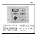
3-1. MOLEL 5261A CONTROLS.
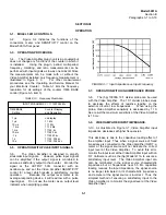
3-2. Figure 3-2 indicates the functions of the
connectors, meter, and SENSITIVITY control on the
Model 5261A front panel.
3-3. OPERATING PROCEDURE.
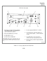
3-4. The Video Amplifier plug-in unit is ac-coupled but
does not change any functions of the counter in which it
is installed. Using the plug-in, period, multi-period,
frequency, totalizing, and ratio measurements can be
performed with input signals as low as one millivolt. Since
the measurements can be made with or without the
Video Amplifier installed, only frequency measurement is
illustrated in Figure 3 3. For other measurement
procedures, see the Operating and Service Manual for
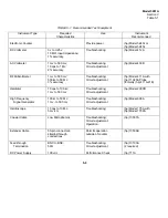
your Electronic Counter. Table 3-1 lists the frequency
resolution for all settings of the counter TIME BASE
control (Figure 3-3, item 3).
TABLE 3-1. Frequency Resolution
INPUT FREQUENCY = 11.1223344 Mc
TIME BASE Counter Display
Setting and Resolution
1
µ
s no display
1
µ
s 11. Mc
10
µ
s 11.1 Mc
.1 ms 11.12 Mc
1 ms 11122. kc
10 ms 11122.3 kc
.1 s 11122.33 kc
1 s 11122. 334 kc
10 s 11122. 3344 kc
3-5. OPERATION WITH PULSE INPUT SIGNALS.
3-6. The Video Amplifier is designed to amplify
sinusoidal input signals. However, pulse input signals
can be amplified if the output signal is monitored to
ensure a satisfactory output to the counter. Monitor the
signal at the OUTPUT 50Q connector with an
oscilloscope and set the Video Amplifier SENSITIVITY
control for a level which results in satisfactory counter
operation. Because the output level meter is an
average-responding device, it will read low with a pulse
input signal. Do not use the meter as an output level
indicator when amplifying pulses.
FIGURE 3-1. Input Impedance vs Input Frequency
3-7. OPERATION WITH HIGH IMPEDANCE PROBE
3-8. The (hp) 10003A 10:1 divider probe can be used
with the Video Amplifier. The 10:1 divider probe serves
to decrease the effects of resistive loading on the
external circuit at low frequencies. When using the
probe, Video Amplifier sensitivity is decreased by 1 10.
As a result the maximum sensitivity of the Video Amplifier
is 10 mv.
3-9. VIDEO AMPLIFIER INPUT IMPEDANCE.
3-10. As illustrated in Figure 3-1, Video Amplifier input
impedance decreases at higher frequencies.
This decrease is due to the capacitive loading effect of
the amplifier input Thus when a signal source of fixed
impedance is connected to the Video Amplifier INPUT, a
meter at the signal source will not indicate the correct
input level at the Video Amplifier. To avoid this error,
monitor the input level at the Video Amplifier input with an
RF Voltmeter such as the (hp) Model 411A to ensure a
satisfactory input level. The Video Amplifier input can
also be terminated in the signal source characteristic
impedance but at frequencies near 50 Mc capacitive
loading reduces the input impedance, the signal source
is no longer terminated in its characteristic impedance,
and a meter at the signal source is incorrect. Thus, the
simplest method of ensuring a satisfactory input to the
Video Amplifier is to monitor the signal level at the Video
Amplifier input.
3-1
Summary of Contents for AM-4380/U 5261A
Page 2: ...A ...
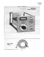
Page 7: ...Model 5261A Section I Figure 1 1 FIGURE 1 1 Model 5261A 1 0 ...
Page 19: ...Model 5261A Section V Figure 5 1 FIGURE 5 1 Schematic Diagram Notes 5 5 ...
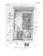
Page 20: ...Model 5261A Section V Figure 5 2 FIGURE 5 2 Top View Component Location 5 6 ...
Page 21: ...Model 5261A FIGURE 5 3 Bottom View Component Location 5 7 ...
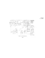
Page 22: ...Model 5261A Section V Figure 5 3 and 5 4 FIGURE 5 4 Video Amplifier Schematic 5 7 5 8 ...
Page 31: ...TM 11 6625 2906 14 P APPENIDIX C Additional Authorization List Not Applicable C 1 ...
Page 39: ...Model 5261A Appendix E FIGURE A 1 Top View Component Location E 3 ...
Page 40: ...Model 5261A Appendix E FIGURE A 2 Bottom View Component Location E 4 ...
Page 41: ...Model 5261A Appendix E FIGURE A 3 Video Amplifier Schematic E 5 ...
Page 42: ...Model 5261A Appendix E FIGURE A 4 A1 Preamplifier Component Location E 6 ...
Page 43: ...Model 5261A Appendix E FIGURE A 5 Video Amplifier Schematic E 7 ...
Page 44: ......
Page 45: ......
Page 47: ......
Page 48: ...PIN 046855 000 ...


