Model 5261A
Section III
Figure 3-2
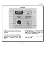
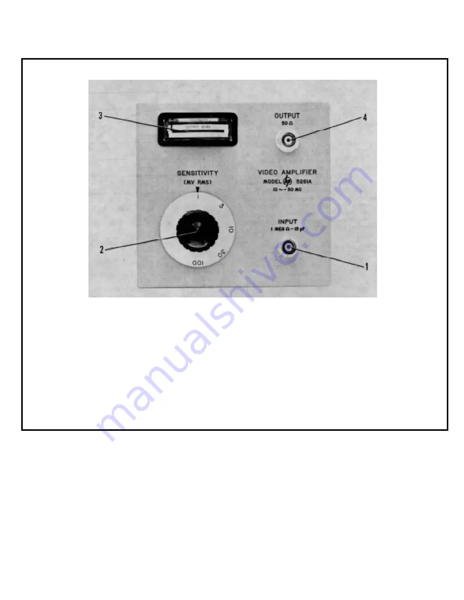
CONTROLS
1. INPUT signal connector: apply a 1-100 mv AC signal
between 10 cps and 20 Mc (5243L) or 10 cps and 50
Mc (5245L).
2. SENSITIVITY control: calibrated in millivolts, this
control determines the sensitivity of the Video
Amplifier and is adjusted to keep the signal output to
the Counter within limits acceptable to the Counter
input circuits as indicated on the OUTPUT LEVEL
meter.
3. OUTPUT LEVEL meter: meter monitors the level of
the Video Amplifier output to the Counter. When
meter indicates in green portion of scale, Video
Amplifier output to Counter is satisfactory.
4. OUTPUT 50
Ω
connector: when terminated in 50
ohms, the signal at this connector is identical in
frequency and amplitude to the Video Amplifier
output to the Counter.
05261-A-6
FIGURE 3-2. Controls
3-2
Summary of Contents for AM-4380/U 5261A
Page 2: ...A ...
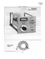
Page 7: ...Model 5261A Section I Figure 1 1 FIGURE 1 1 Model 5261A 1 0 ...
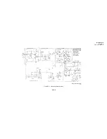
Page 19: ...Model 5261A Section V Figure 5 1 FIGURE 5 1 Schematic Diagram Notes 5 5 ...
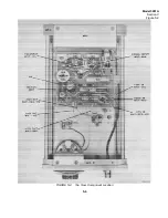
Page 20: ...Model 5261A Section V Figure 5 2 FIGURE 5 2 Top View Component Location 5 6 ...
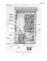
Page 21: ...Model 5261A FIGURE 5 3 Bottom View Component Location 5 7 ...
Page 22: ...Model 5261A Section V Figure 5 3 and 5 4 FIGURE 5 4 Video Amplifier Schematic 5 7 5 8 ...
Page 31: ...TM 11 6625 2906 14 P APPENIDIX C Additional Authorization List Not Applicable C 1 ...
Page 39: ...Model 5261A Appendix E FIGURE A 1 Top View Component Location E 3 ...
Page 40: ...Model 5261A Appendix E FIGURE A 2 Bottom View Component Location E 4 ...
Page 41: ...Model 5261A Appendix E FIGURE A 3 Video Amplifier Schematic E 5 ...
Page 42: ...Model 5261A Appendix E FIGURE A 4 A1 Preamplifier Component Location E 6 ...
Page 43: ...Model 5261A Appendix E FIGURE A 5 Video Amplifier Schematic E 7 ...
Page 44: ......
Page 45: ......
Page 47: ......
Page 48: ...PIN 046855 000 ...


