Model 5261A
Section V
Paragraphs 5-14 to 5-18
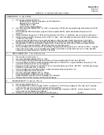
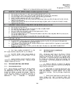
TABLE 5-2. In-Cabinet Performance Checks (cont’d)
4.
MONITOR: OUTPUT METER indicates acceptable signal level to Counter
a.
Set Counter controls as in 1 a and Video Amplifier SENSITIVITY to 3 ’MV.
b. Set Oscillator to 100 kc and connect to Video Amplifier INPUT with 50-ohm termination.
c. Connect Voltmeter to 50 19 OUTPUT with 50-ohm feedthrough termination.
d
Adjust Oscillator output level for 420 mv on Voltmeter
e. Observe that OUTPUT LEVEL meter indicates at right edge of green portion of scale and Counter correctly
displays input frequency.
g
Observe that OUTPUT LEVEL meter indicates at left edge of green portion of scale and Counter correctly
displays input frequency.
5.
ACCURACY: retains accuracy of Model 5243L or Model 5245L Electronic Counter.
a. Set Counter controls as in 1 a.
b. Set Oscillator frequency to 100 kc and connect to Video Amplifier INPUT.
c. Set Video Amplifier SENSITIVITY to 100 MV.
d. Connect Voltmeter to Oscillator output and set signal level to 100 mv.
e. Observe and record Counter display.
f. Set Counter SENSITIVITY to .1V. Disconnect Oscillator output from Video Amplifier INPUT and connect to
Counter AC SIGNAL INPUT.
g. Observe that Counter display corresponds with value recorded in step e.
6.
AUXILIARY OUTPUT’
a. 50
Ω
OUTPUT on front panel lor monitoring amplified signal to Counter or for driving external equipment
checked in 1 under BANDWIDTH specification check.
b. 1 mv signal at Video Amplifier INPUT provides at least 100 mv at 50
Ω
OUTPUT, checked in 2 under INPUT
SENSITIVITY specification check.
c. Maximum undistorted output is 300 my into 50-ohhm load, checked in 2 under INPUT SENSITIVITY
specification check.
d. Set Video Amplifier SENSITIVITY to 100
MV. Adjust Oscillator output for 420 mv on Voltmeter.
e. OUTPUT LEVEL meter should indicate at
right edge of green scale. If not, adjust A4R13 for this
indication.
f.
Adjust Oscillator output for OUTPUT LEVEL
indication at left edge of green scale. Voltmeter should
indicate not less than 100 mv.
5-14. TROUBLESHOOTING AND REPAIR.
5-15. TROUBLESHOOTING.
5-16. When operation or performance checks indicate
an instrument malfunction, refer to Table 5-3
(Troubleshooting) for the more common indications of
trouble and checks to isolate the trouble. After the
trouble has been isolated to a particular assembly or
stage, voltage and resistance checks can be made to
determine the defective component.
5-17.
PRINTED CIRCUIT COMPONENT
REPLACEMENT.
5-18. Component lead holes in the Mode I 5261A
printed circuit boards have plated walls to ensure good
electrical contact between conductors on opposite sides
of the board. To prevent damage to this plating and to
the replacement component, apply heat sparingly and
work carefully. The following replacement procedure is
recommended:
a. Remove defective component by applying
heat carefully to the component connection and lifting the
component from the board.
b. Melt solder in component lead holes. Use
clean dry soldering iron to remove excess solder. Clean
holes with toothpick or wooden splinter. Do not use
metal tool for cleaning. This may damage through-hole
plating.
c. Bend lead of replacement component to the
correct shape and insert component leads into
component lead holes. Using heat and solder sparingly,
solder
5-3
Summary of Contents for AM-4380/U 5261A
Page 2: ...A ...
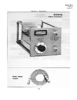
Page 7: ...Model 5261A Section I Figure 1 1 FIGURE 1 1 Model 5261A 1 0 ...
Page 19: ...Model 5261A Section V Figure 5 1 FIGURE 5 1 Schematic Diagram Notes 5 5 ...
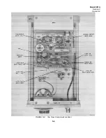
Page 20: ...Model 5261A Section V Figure 5 2 FIGURE 5 2 Top View Component Location 5 6 ...
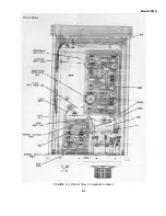
Page 21: ...Model 5261A FIGURE 5 3 Bottom View Component Location 5 7 ...
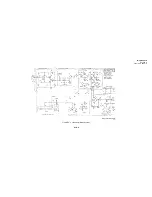
Page 22: ...Model 5261A Section V Figure 5 3 and 5 4 FIGURE 5 4 Video Amplifier Schematic 5 7 5 8 ...
Page 31: ...TM 11 6625 2906 14 P APPENIDIX C Additional Authorization List Not Applicable C 1 ...
Page 39: ...Model 5261A Appendix E FIGURE A 1 Top View Component Location E 3 ...
Page 40: ...Model 5261A Appendix E FIGURE A 2 Bottom View Component Location E 4 ...
Page 41: ...Model 5261A Appendix E FIGURE A 3 Video Amplifier Schematic E 5 ...
Page 42: ...Model 5261A Appendix E FIGURE A 4 A1 Preamplifier Component Location E 6 ...
Page 43: ...Model 5261A Appendix E FIGURE A 5 Video Amplifier Schematic E 7 ...
Page 44: ......
Page 45: ......
Page 47: ......
Page 48: ...PIN 046855 000 ...

