TM 11-6625-2906-14 & P
SECTION 0
INTRODUCTION
0-1.
SCOPE.
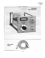
a. This manual describes Video Amplifier AM-
4380/U (fig. 1-1) and provides maintenance
instructions. Throughout this manual, AM-
4380/U is referred to as the Hewlett-Packard
(HP) Model 5261A Video Amplifier.
0-2.
INDEXES OF PUBLICATIONS.
a.
DA Pam 310-4.
Refer to the latest issue of
DA Pam 310-4 to determine whether there are new
editions, changes, or additional publications pertaining to
the equipment.
b.
DA Pam 310-7.
Refer to DA Pam 310-7 to
determine whether there are modification work orders
(MWO’s) pertaining to the equipment.
0-3. FORMS AND RECORDS.
a.
Reports of Maintenance and Unsatisfactory
Equipment.
Maintenance forms, records, and reports
which are to be used by maintenance personnel at all
maintenance levels are listed in and prescribed by TM
38-750.
b.
Report of Packaging and Handling
Deficiencies.
Fill out and forward DD Form 6
(Packaging Improvement Report) as prescribed in AR
70058/NAVSUPINST 4030.29/AFR 71-13/MCO
P4030.29A and DLAR 4145.8.
c.
Discrepancy in Shipment Report (DISREP)
(SF 361).
Fill out and forward Discrepancy in Shipment
Report (DISREP) (SF 361) as prescribed in AR 55-
38/NAVSUPINST 4610.33B/AFR 7518/MCO P4610.19C
and DLAR 4500.15.
0-4.
REPORTING EQUIPMENT IMPROVEMENT
RECOMMENDATIONS (EIR).
EIR’s will be prepared using SF 368 (Quality Deficiency
Report). Instructions for preparing EIR’s are provided in
TN) 38-750, the Army Maintenance Management
System. ElR’s should be mailed direct to Commander,
US Army Communication and Electronics Materiel
Readiness Command, ATTN: DRSEL-NIE-NIQ, Fort
Monmouth, NJ 07703. A reply will be furnished direct to
you.
0-5.
ADMINISTRATIVE STORAGE.
Administrative storage of equipment issued to and used
by Army activities shall be in accordance with T%, 740-
90-1 and paragraph 2-8.
0-6.
DESTRUCTION OF ARMY ELECTRONICS
MATERIEL.
Destruction of Army electronics materiel to prevent
enemy use shall be in accordance with TM 750-244-2.
0-1
Summary of Contents for AM-4380/U 5261A
Page 2: ...A ...
Page 7: ...Model 5261A Section I Figure 1 1 FIGURE 1 1 Model 5261A 1 0 ...
Page 19: ...Model 5261A Section V Figure 5 1 FIGURE 5 1 Schematic Diagram Notes 5 5 ...
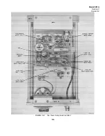
Page 20: ...Model 5261A Section V Figure 5 2 FIGURE 5 2 Top View Component Location 5 6 ...
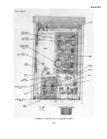
Page 21: ...Model 5261A FIGURE 5 3 Bottom View Component Location 5 7 ...
Page 22: ...Model 5261A Section V Figure 5 3 and 5 4 FIGURE 5 4 Video Amplifier Schematic 5 7 5 8 ...
Page 31: ...TM 11 6625 2906 14 P APPENIDIX C Additional Authorization List Not Applicable C 1 ...
Page 39: ...Model 5261A Appendix E FIGURE A 1 Top View Component Location E 3 ...
Page 40: ...Model 5261A Appendix E FIGURE A 2 Bottom View Component Location E 4 ...
Page 41: ...Model 5261A Appendix E FIGURE A 3 Video Amplifier Schematic E 5 ...
Page 42: ...Model 5261A Appendix E FIGURE A 4 A1 Preamplifier Component Location E 6 ...
Page 43: ...Model 5261A Appendix E FIGURE A 5 Video Amplifier Schematic E 7 ...
Page 44: ......
Page 45: ......
Page 47: ......
Page 48: ...PIN 046855 000 ...


