background image

MF877-00                                                                                                Page  2 
Template Revision C, 30-July-2018 


Copyright 2018 Hewlett Packard Enterprise Development LP


HPE instructions for this template are available a

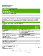
MF877-01


Item Description 

Notes 

Quantity 
of items 
included 
in product


Components and parts containing toner and ink, 
including liquids, semi-liquids (gel/paste) and toner 

Include the cartridges, print heads, tubes, vent 
chambers, and service stations.             

Components and waste containing asbestos 


Components, parts and materials containing 
refractory ceramic fibers 


Components, parts and materials containing 
radioactive substances 


2.0 Tools Required


List the type and size of the tools that would typically be used to disassemble the product to a point where components 
and materials requiring selective treatment can be removed. 

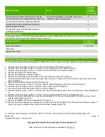
Tool Description 

Tool Size (if 
applicable) 

Torx Screw Drivers 

 T-10, T-15 

Wire snips 


Needle nose pliers 


3.0 Product Disassembly Process


3.1 List the basic steps that should typically be followed to remove components and materials requiring selective treatment:  

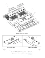
1.  Unscrew the screws (qty 18) with a T-10 driver, from the top of the chassis (Figure 1) 
2.  Unscrew the screws (qty 3) with a T-10 driver, from the right side of the chassis (Figure 1) 
3.  Unscrew the screws (qty 3) with a T-10 driver, from the left side of the chassis (Figure 1) 
4.  Remove the lid from the chassis base 
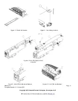
5.  Remove the plastic tab fr chassis (Figure 2) 
6.  Remove the coin battery from its holder on the right side of the main PCA (Figure 3) 
7.  Cut cable tie with wire snips, remove the screw (qty 1) with a T-10 driver, from the PCA at the rear right corner of the 

switch (Figure 4) 

8.  Disconnect the cable and remove the PCA (Figure 4) 
9.  Unscrew the screw (qty 1) with a T-10 driver, and the bracket that were under the rear PCA (Figure 5) 
10.  Unscrew the screw (qty 2) with a T-10 driver, and remove front PCA (Figure 6) 
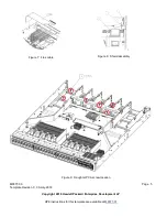
11.  Use force to pull out the flex cable fr the 2 connector (Figure 7) 
12.  Unscrew the screw (qty 1) with a T-10 driver, from the front left chassis, and remove the shield cover and shield (Figure 

8) 

13.  Unscrew the screws (qty 6) with a T-10 driver, that secure the daughter PCA to the base (Figure 9) 
14.  Remove the sheet metal parts that is securing the daughter PCA, remove the daughter PCA and then remove the 2 

plastic airflow baffle (Figure 10) 

15.  Remove the DIMM PCA from the daughter PCA (Figure 11) 
16.  Remove the small heatsink by unclipping the two wire bails from the daughter PCA, then twist and untwist a couple of 

times to remove the heatsink from the thermal interface material (Figure 12) 


17.  Unscrew the screws (qty 2) at the side, with a T-10 driver, and remove the left and right air baffle (Figure 13) 

Summary of Contents for Aruba 8360-48Y6C v2

Page 1: ... treatment 1 2 Enter the quantity of items contained within the product which require selective treatment in the right column as applicable Item Description Notes Quantity of items included in product Printed Circuit Boards PCB or Printed Circuit Assemblies PCA With a surface greater than 10 sq cm 4 Batteries All types including standard alkaline and lithium coin or button style batteries 1 Mercur...

Page 2: ...1 3 Unscrew the screws qty 3 with a T 10 driver from the left side of the chassis Figure 1 4 Remove the lid from the chassis base 5 Remove the plastic tab fr chassis Figure 2 6 Remove the coin battery from its holder on the right side of the main PCA Figure 3 7 Cut cable tie with wire snips remove the screw qty 1 with a T 10 driver from the PCA at the rear right corner of the switch Figure 4 8 Dis...

Page 3: ...e of times to remove the heatsink from the thermal interface material and unscrew the 8 screws fr the heatsink and remove the heatsink by twisting and untwisting a couple of times Figure 15 20 At the front right corner of the main PCA remove the front plastic lightpiple Figure 16 21 On the empty chassis front right remove the 2 lightpipe Figure 17 3 2 Optional Graphic If the disassembly process is...

Page 4: ...tt Packard Enterprise Development LP HPE instructions for this template are available at MF877 01 Figure 2 Plastic tab location Figure 4 Rear PCA fastener and connector Figure 5 Rear PCA bracket and fastener Figure 3 Coin battery location Figure 6 Front PCA and fastener ...

Page 5: ...e Revision C 30 July 2018 Copyright 2018 Hewlett Packard Enterprise Development LP HPE instructions for this template are available at MF877 01 Figure 7 Flex cable Figure 8 Shield assembly Figure 9 Daughter PCA screw location ...

Page 6: ...ate Revision C 30 July 2018 Copyright 2018 Hewlett Packard Enterprise Development LP HPE instructions for this template are available at MF877 01 Figure 10 Daughter PCA removal Figure 11 Flex cable Figure 12 Shield assembly ...

Page 7: ...77 00 Page 7 Template Revision C 30 July 2018 Copyright 2018 Hewlett Packard Enterprise Development LP HPE instructions for this template are available at MF877 01 Figure 13 Left and right air baffle reval ...

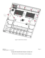
Page 8: ...MF877 00 Page 8 Template Revision C 30 July 2018 Copyright 2018 Hewlett Packard Enterprise Development LP HPE instructions for this template are available at MF877 01 Figure 14 Main PCA screw location ...

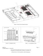
Page 9: ...C 30 July 2018 Copyright 2018 Hewlett Packard Enterprise Development LP HPE instructions for this template are available at MF877 01 Figure 15 Main PCA and heatsink removal Figure 16 Light pipe Removal Figure 17 Front light pipe removal ...

Reviews: