MF877-00 Page 2
Template Revision C, 30-July-2018
Copyright 2018 Hewlett Packard Enterprise Development LP
HPE instructions for this template are available at
2.0 Tools Required
List the type and size of the tools that would typically be used to disassemble the product to a point where components
and materials requiring selective treatment can be removed.
Tool Description
Tool Size (if
applicable)
Phillips Screw Driver
P1 ,P2
Diagonal pliers
5
”
Socket Screw Driver
5.0mm ,5.5mm
3.0 Product Disassembly Process
3.1 List the basic steps that should typically be followed to remove components and materials requiring selective treatment:
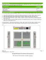
1. Using a P1 Phillips Screw Driver, remove all 8 screws securing top cover to chassis. Remove Cover. (see 3.2.1)
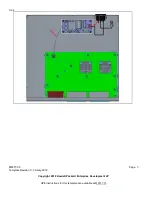
2. Disconnect Power supply and main board cable connections (2 cables connections in all). (see 3.2.2)
3. Using a P2 Phillips Screw Driver, remove 4 screws to chassis, remove Power supply (1pcs). (see 3.2.3)
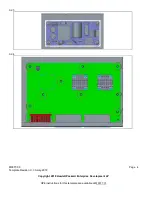
4. Using a P2 Phillips Screw Driver, remove 9 screws to chassis, remove main board (1pcs) and light-pipe assembly
(1pcs). (see 3.2.4)
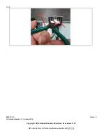
5. Cut ac-inlet materials (use Diagonal pliers) and Using a P2 Phillips Screw Driver, remove 1 screws to chassis and
Disconnect ac-inlet cable(see 3.2.5)
3.2 Optional Graphic. If the disassembly process is complex, insert a graphic illustration below to identify the items
contained in the product that require selective treatment (with descriptions and arrows identifying locations).
3.2.1

