Installation
ASSEMBLY INSTRUCTIONS
Attach the wood side panels to the amplifier
with the Allen screws and nuts. It will be noted
that the side panels are notched across one end
to clear the front panel overhang and to allow the
wood panel to extend slightly forward of the
front panel. Near one edge of each wood panel
is a slot extending the full length. The panel should
be attached so that these slots are at the top of the
amplifier and face inboard.
The aluminum top cover slides into the slots
just mentioned, with the front edge fitting into a
slot at the top rear of the front panel.
The rear edge of the top cover lies on the
top of the back panel and is secured with a single
3-4
The Barney Oliver Audio Amplifier
screw through the top cover. It may be necessary
to adjust the positions of the wood side panels to
permit the top cover to slide into place without
interference from side gussets or other amplifier
parts.
I.
RACK MOUNTING CABINET
If your amplifier was furnished in an HP
type cabinet, it can be rack mounted by use of
the standard rack mount kit shipped with the
instrument. Instructions are included with the kit.
J.
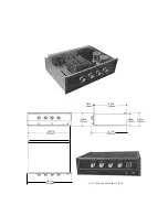
PICTURES AND OUTLINE DRAWING
(See following page.)
Summary of Contents for Barney Oliver
Page 1: ... 3 AMPLIfIER ...
Page 11: ... ____ 10 93in 278 NOTE CASE IS AN EXTRA PRICE OPTION ...
Page 16: ...eTION V I IR UIT DIAGRAMS ...


