background image

13

Replacing the System Board

Removing the System Board

2

Pull the system board down from the top until it is laying flat, as in one of the 
pictures below.

3

Remove all cables from the board.

Summary of Contents for Brio BA

Page 1: ...http www hp com go briosupport Upgrade Guide HP Brio PCs BA BAx ...

Page 2: ...damages in connection with the furnishing performance or use of this material This document contains proprietary information that is protected by copyright All rights are reserved No part of this document may be photocopied reproduced or translated into another language without the prior written consent of Hewlett Packard Company Microsoft MS DOS and Windows are U S registered trademarks of Micros...

Page 3: ...he System Board 15 4 Replacing the Floppy Drive 17 Removing the Floppy Drive 18 Replacing the Floppy Disk Drive 19 5 Replacing the Hard Disk Drive 21 Removing the Hard Disk Drive 22 Replacing the Hard Disk Drive 24 6 Replacing a 5 25 Bay Disk Drive 25 Installing an Expansion Bay Drive 26 Removing an Expansion Bay Drive 30 7 Replacing a Memory Module 33 Installing a Memory Module 34 Removing a Memo...

Page 4: ...cing the Video RAM 37 Replacing the VRAM Module 38 9 Replacing Expansion Cards 41 Installing an Expansion Card 42 Removing an Expansion Card 43 10 Replacing the Power Supply Unit 45 11 Replacing the Processor 49 ...

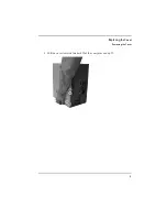
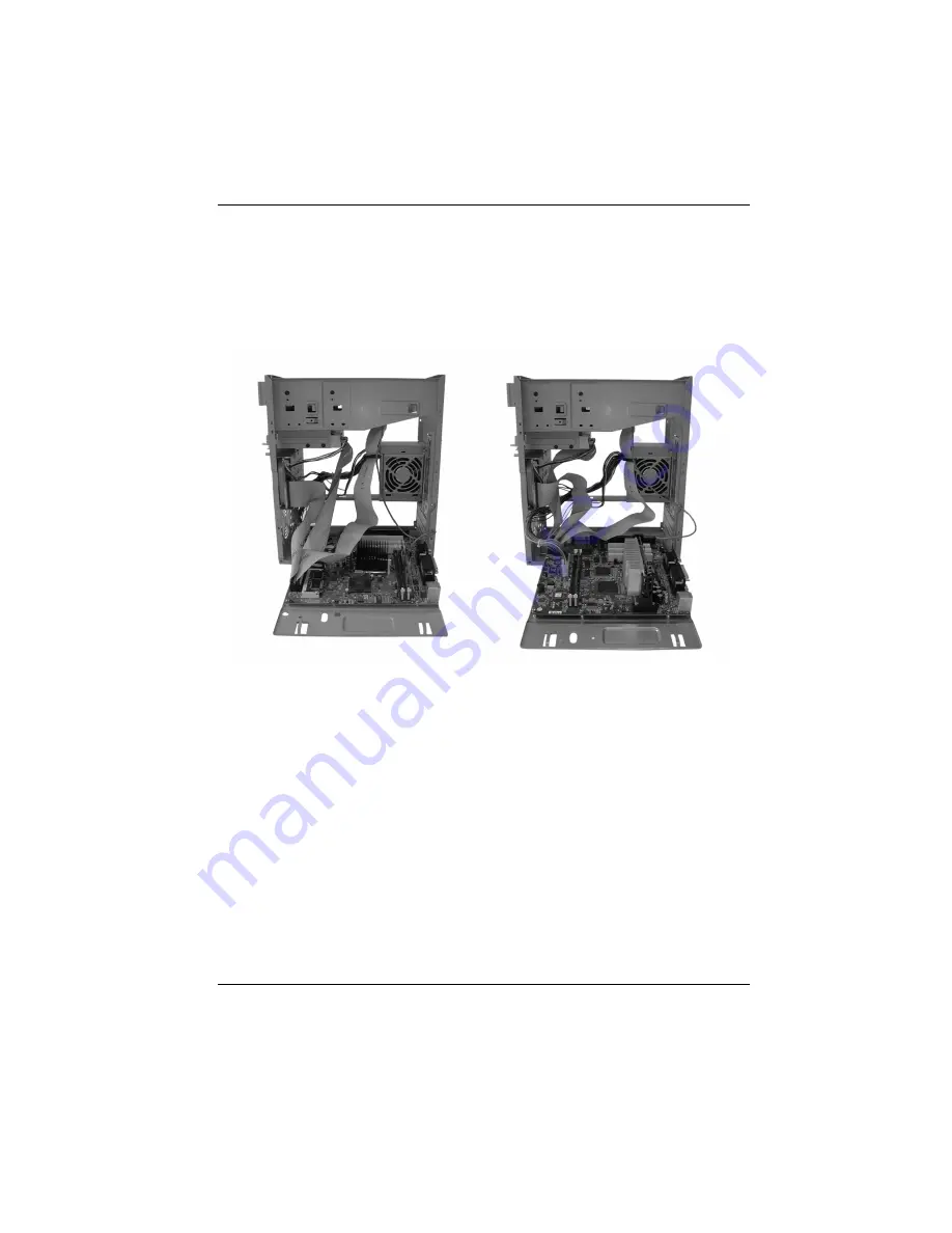
Page 5: ...5 Inside the Computer 1 ...

Page 6: ...mputer Inside the Computer Inside the Computer The following components are inside your computer 1 Hard disk drive bay 2 Floppy disk drive bay 3 5 25 drive expansion bays 4 System board 5 Power supply unit 6 Expansion card bay ...

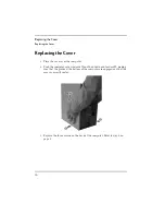
Page 7: ...7 Replacing the Cover 2 ...

Page 8: ...l need a flat area such as a table to rest the computer on 1 Disconnect all of the cables from the computer 2 Remove the three screws on the back of the computer by unscrewing them with your hand Caution For your safety disconnect the power cord and all external cables ...

Page 9: ...9 Replacing the Cover Removing the Cover 3 Pull the cover towards the back of the computer and up ...

Page 10: ...e cover over the computer 2 Push the computer cover inwards and then down and forward making sure that the guides at the bottom of the computer are engaged and that the case is correctly seated 3 Replace the three screws on the back of the computer Refer to step 2 on page 8 ...

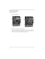
Page 11: ...11 Replacing the System Board 3 ...

Page 12: ...Remove the two screws Warning If your old system board contains a lithium battery do not dispose of it in household waste Please return batteries to the shop from which you bought them to the dealer from whom you purchased your PC or to HP so they can be recycled or disposed of in a sound way Returned used batteries will be accepted free of charge Caution For your safety disconnect the power cord ...

Page 13: ...13 Replacing the System Board Removing the System Board 2 Pull the system board down from the top until it is laying flat as in one of the pictures below 3 Remove all cables from the board ...

Page 14: ... 4 Remove the eight screws 5 Lift the system board out of the computer 6 Remove any exchangeable components such as the processor memory modules or video memory modules Refer to the appropriate chapters for instructions on removing the individual components ...

Page 15: ...er to the appropriate chapters for instructions on inserting the individual components The Procedure 1 Place the system board onto its base 2 Replace the eight screws Refer to step 4 on page 14 for the location of the screws 3 Replace the cables into their appropriate sockets The connectors are keyed and can only fit into the sockets in one direction 4 Replace the system board into the computer ma...

Page 16: ...16 Replacing the System Board Replacing the System Board 5 Slide the system board towards the front of the computer 6 Replace the screws 7 Replace the cover ...

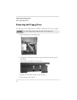
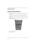
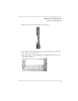
Page 17: ...17 Replacing the Floppy Drive 4 ...

Page 18: ...e Cover on page 8 1 Undo the floppy drive bay fixing screw 2 Pull the bay towards the back of the computer until it is released from its mountings 3 Undo the four screws two on each side 4 Remove the two cables form the back of the drive 5 Slide the drive out of the bay Caution For your safety disconnect the power cord and all external cables ...

Page 19: ...ure that the connectors on the rear of the drive are at the back of the bay 2 Replace the two drive cables 3 Replace the four screws Refer to step 3 on page 18 for the location of the screws 4 Slide the drive into the computer making sure that the slots are located on the tags 5 Replace the floppy drive bay fixing screw 6 Replace the cover ...

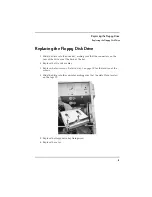
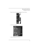
Page 20: ...20 Replacing the Floppy Drive Replacing the Floppy Disk Drive ...

Page 21: ... Hard Disk Drive This chapter explains how to remove and replace the hard disk drive If you wish to install or replace a second hard drive then you must refer to the chapter Replacing a 5 25 Bay Disk Drive on page 25 5 ...

Page 22: ...eed to have removed the cover Refer to Removing the Cover on page 8 1 Remove the hard drive bay fixing screw 2 Slide the drive bay towards the cables until the bay is out of its mounts and then pull the drive out of the computer Caution For your safety disconnect the power cord and all external cables ...

Page 23: ...23 Replacing the Hard Disk Drive Removing the Hard Disk Drive 3 Remove the power and data cables from the hard disk drive 4 Undo the four screws 5 Slide the hard disk drive out of the bay ...

Page 24: ...e that the drive is correctly mounted 2 Fit the four screws Refer to step 4 on page 23 for the screw positions 3 Replace the power and data cables Refer to step 1 on page 22 for the cable positions 4 Replace the bay into the computer making sure that the tags are correctly engaged in their holes 5 Replace the bay fixing screw 6 Replace the cover ...

Page 25: ...o remove and install drives into the two 5 25 drive bays These bays can hold CD ROM DVD Hard Disk or Zip drives If you wish to replace the hard disk drive that came pre installed in your computer then refer to the chapter Replacing the Hard Disk Drive on page 21 6 ...

Page 26: ...bay you wish to use is the bottom bay or you wish to use the top bay and it is empty then remove the front of the computer by first releasing the two clips on the top of the computer Otherwise go to step 7 on page 28 Caution For your safety disconnect the power cord and all external cables When installing a CDROM drive to avoid electric shock and damage to your eyes by laser light do not open the ...

Page 27: ... 3 Release the two clips on either side of the computer 4 Lay the front cover down in front of the computer taking care of the cables that connect to the system board 5 Remove the plastic drive blanking plate by pushing the clips outwards and then lifting the plate out ...

Page 28: ...river 7 If the bottom bay is to be used then slide the drive in from the front of the computer Otherwise slide the drive in from the rear 8 Fit the four screws two on each side as shown below shows the position of the top bay screws and for the bottom these are shown with the system board removed It is not necessary to remove the system board ...

Page 29: ...cing a 5 25 Bay Disk Drive Installing an Expansion Bay Drive 9 Connect the audio only if you install a CDROM or DVD drive data and power drive cables 10 Replace the cover Refer to Replacing the Cover on page 10 ...

Page 30: ...eed to have removed the cover Refer to Removing the Cover on page 8 1 If you are removing a drive from the bottom drive bay then remove the front of the computer by first releasing the two clips on the top of the computer Otherwise go to step 5 on page 31 2 Release the two clips on either side of the computer ...

Page 31: ...n place a plastic blanking plate into the cover if one is available 5 Remove the drive cables Refer to step 9 on page 29 for the location of the cables 6 Remove the four screws from the drive Refer to step 8 on page 28 for the location of the screws 7 If the drive is in the bottom bay then slide the drive out from the front of the computer Otherwise slide the drive out from the rear 8 Replace the ...

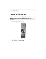
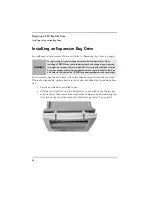
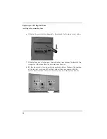
Page 32: ...32 Replacing a 5 25 Bay Disk Drive Removing an Expansion Bay Drive ...

Page 33: ...33 Replacing a Memory Module 7 ...

Page 34: ...e System Board on page 12 You do not need to remove the cables from the system board as in step 3 on page 13 The Procedure 1 Locate an empty memory module socket 2 Make sure that the socket s clips are open 3 Holding the memory module by its longest edges slide it into the socket It is keyed and can only go in to the socket in one direction Caution For your safety disconnect the power cord and all...

Page 35: ...Module Installing a Memory Module 4 Push down the memory module until the clips are closed 5 Replace the system board Refer to Replacing the System Board on page 15 6 Replace the cover Refer to Replacing the Cover on page 10 ...

Page 36: ...s from the system board as in step 3 on page 13 The Procedure 1 Locate the memory module that you wish to remove 2 Open both clips at each end of the module Refer to step 2 on page 34 3 Holding the memory module by its longest edges pull it up and out of the socket 4 Replace the system board Refer to Replacing the System Board on page 15 5 Replace the cover Refer to Replacing the Cover on page 10 ...

Page 37: ...37 Replacing the Video RAM You only need to replace the VRAM Video RAM in the HP Brio PC BA model 8 ...

Page 38: ...ver Refer to Removing the Cover on page 8 to have removed the system board Refer to Removing the System Board on page 12 You do not need to remove the cables from the system board as in step 3 on page 13 The Procedure 1 Locate the VRAM module Caution For your safety disconnect the power cord and all external cables ...

Page 39: ...st edges lift it up and out of the socket 4 Slide the new module into the socket making sure that the side with the IC s is uppermost 5 Push the module down until it is properly seated 6 Replace the system board Refer to Replacing the System Board on page 15 7 Replace the cover Refer to Replacing the Cover on page 10 ...

Page 40: ...40 Replacing the Video RAM Replacing the VRAM Module ...

Page 41: ...41 Replacing Expansion Cards 9 ...

Page 42: ...ocated in the long black socket otherwise the card is located in the shorter white sockets 2 Remove the blanking plate for the socket by moving the fixing screw and then pulling the plate up and out of the socket 3 Push the card into the socket making sure that it is firmly seated 4 Replace the screw 5 Replace the cover Refer to Replacing the Cover on page 10 Caution For you safety disconnect the ...

Page 43: ...oving the Cover on page 8 1 Locate the expansion card 2 Remove the expansion card s fixing screw Refer to step 2 on page 42 3 Place a blanking plate in the computer if available 4 Replace the fixing screw 5 Replace the cover Refer to Replacing the Cover on page 10 Caution For you safety disconnect the power cord and all external cables ...

Page 44: ...44 Replacing Expansion Cards Removing an Expansion Card ...

Page 45: ...45 Replacing the Power Supply Unit 10 ...

Page 46: ...d system board 3 Slide the power supply unit up and out of the computer Replacing the Power Supply Unit 1 Reconnect all the power cables to the drives and the system board 2 Place the new Power Supply Unit inside the computer making sure that the socket faces the back of the computer and that the cables are inside the computer 3 Replace the three screws Refer to step 1 on page 46 4 Replace the cov...

Page 47: ...47 Replacing the Power Supply Unit 5 Check that the switch voltage of the PSU is set to the correct value for the country that you are in ...

Page 48: ...48 Replacing the Power Supply Unit ...

Page 49: ...49 Replacing the Processor Details on how to replace the Processor or CPU central processing unit can be found in your Online Reference Guide Upgrading a Processor or www hp com go briosupport 11 ...

Page 50: ...50 Replacing the Processor ...

Page 51: ......

Page 52: ... Paper not bleached with chlorine Part Number 5967 9523V2 Printed in ...

Reviews: