NOTE:
Each time the 8Gb SAN Switch is powered on, its settings are restored to the last saved con
fi
guration.
Interpreting LED activity
You can monitor switch activity and status by checking 8Gb SAN Switch LEDs.
There are three possible LED states: no light, a steady light, or a
fl
ashing light. The steady lights and
fl
ashing lights can be green or amber.
The LEDs
fl
ash any of these colors during boot, POST, or other diagnostic tests. This is normal and
does not indicate a problem unless the LEDs do not indicate a healthy state after all boot processes
and diagnostic tests are complete. A healthy state is indicated by a steady green light. See
Table
15
, page 35 for details about LED activity.
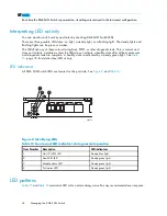
LED indicators
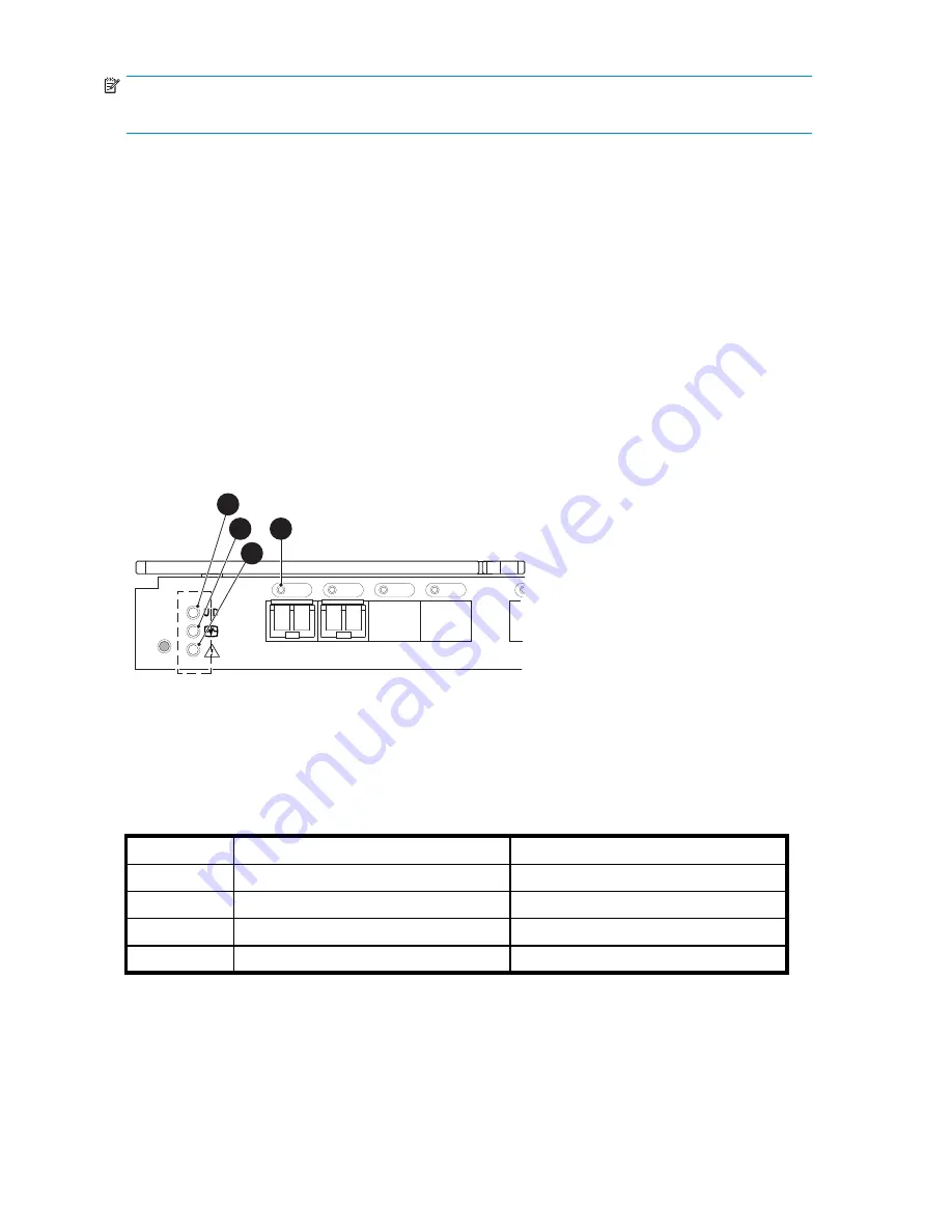
All 8Gb SAN Switch LEDs are located on the port side. See
Figure 8
and
Table 14
.
scale: 1" = 1"
17
18
19
20
!
Reset
26477a
1
2
3
4
Figure 8 Identifying LEDs
Table 14 Front panel LED indicators during normal operation
Item Number Description
LED indicators
1
Unit ID (UID) LED
Steady blue light
2
Health ID LED
Steady green light
3
Module status LED
Steady green light
4
Port status LED
Steady green light
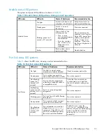
LED patterns
Table 15
and
Table 16
summarize LED color, and meaning, as well as any recommended user response.
34
Managing the 8Gb SAN Switch
Summary of Contents for Brocade 8Gb SAN
Page 5: ...Index 61 Brocade 8Gb SAN Switch for HP BladeSystem c Class 5 ...
Page 8: ...8 ...
Page 12: ...12 About this guide ...
Page 18: ...18 Overview ...
Page 40: ...40 Managing the 8Gb SAN Switch ...
Page 46: ...46 Regulatory compliance and safety ...
Page 48: ...48 Electrostatic discharge ...
Page 52: ...52 SAN Switch technical specifications ...
Page 60: ...60 Glossary ...


